Measuring RF Impedances Throughout the HF and VHF Spectrum
Measuring RF Impedances
Page content last updated Apr. 19, 2015
Copyright © 2015 Larry Benko, W0QE
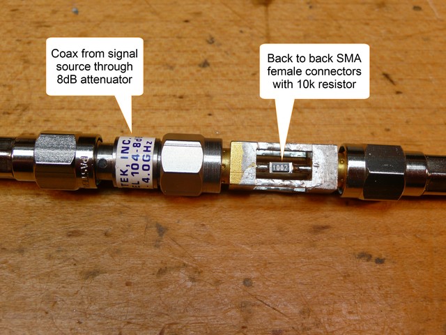
The actual circuit included coax to a 2 port network analyzer and an 8dB attenuator on the transmission side of the circuit to keep the coax SWR low (<1.38:1). The fixture with the 2 SMA female back to back connectors was fitted with a small piece of copper strap and the analyzer was normalized over frequency. Then the strap was replaced with the 10k resistor as shown in the picture and the circuit swept from 1 to 500MHz.
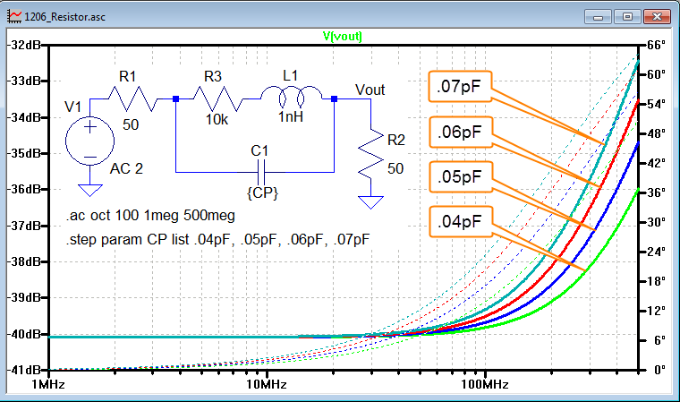
The graph shows the expected low frequency amplitude and an amplitude increase of 5.7dB at 500MHz which represents a shunt capacitance of .055pF and agrees very closely with my prevous tests. Sweeping other resistor values resulted in different low frequency amplitudes based on the resistance but still showed capacitances of approximately .055pF.
Test Format
I obtained reels of 0.5% or better 1206 SMD resistors and measured them at DC with a 6.5 digit meter and found them all to be well within spec. Resistors of values 10, 100, 1k, and 10k ohms were used as being reresentative of impedances that might be encountered.
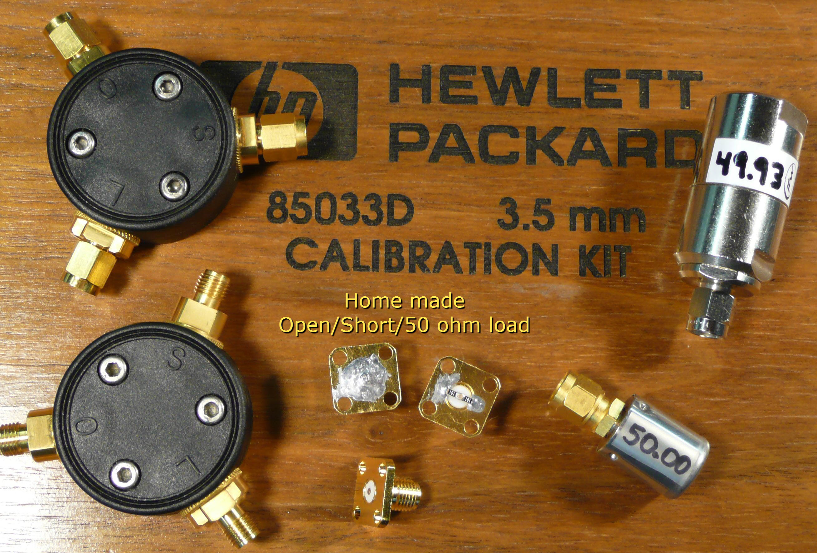
Having done this exercise previously I am aware of some of the pitfalls when trying to make reasonably accurate measurements so I approached the challenge somewhat differently than others might do. I started with the best calibration I could do using the best set of calibration loads and the best test fixture I could come up with to start. The picture below shows two HP 3.5mm (compatible with SMA) cal kits, the home made OSL (Open/Short/Load) SMA female cal kit, and two other precision 50 ohm SMA loads.
I obtained reels of 0.5% or better 1206 SMD resistors and measured them at DC with a 6.5 digit meter and found them all to be well within spec. Resistors of values 10, 100, 1k, and 10k ohms were used as being reresentative of impedances that might be encountered.
Having done this exercise previously I am aware of some of the pitfalls when trying to make reasonably accurate measurements so I approached the challenge somewhat differently than others might do. I started with the best calibration I could do using the best set of calibration loads and the best test fixture I could come up with to start. The picture below shows two HP 3.5mm (compatible with SMA) cal kits, the home made OSL (Open/Short/Load) SMA female cal kit, and two other precision 50 ohm SMA loads.
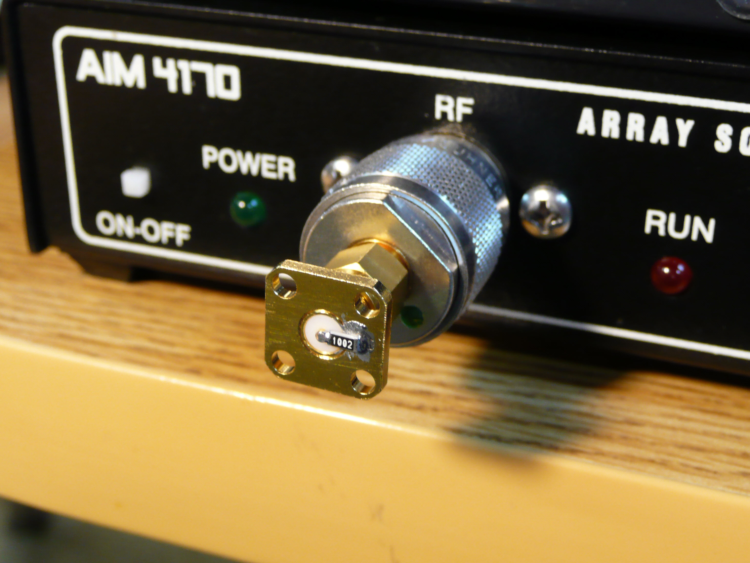
Using the HP 3.5mm female cal kit and a high quality Suhner N-male to SMA-male adapter was the first test done. The HP cal kit needed +0.20cm of line extension (50 ohm VF=1) to show opens and shorts with no phase rotation vs frequency. This correction placed the reference plane at the flat edge of the gold SMA female connectors for my test fixture as shown in the picture below. Later tests done with my home made SMA cal kit produced nearly identical results. No line extension was required for my home made cal kit since the cal kit and test fixture were on identical connectors.
Initial Test Results
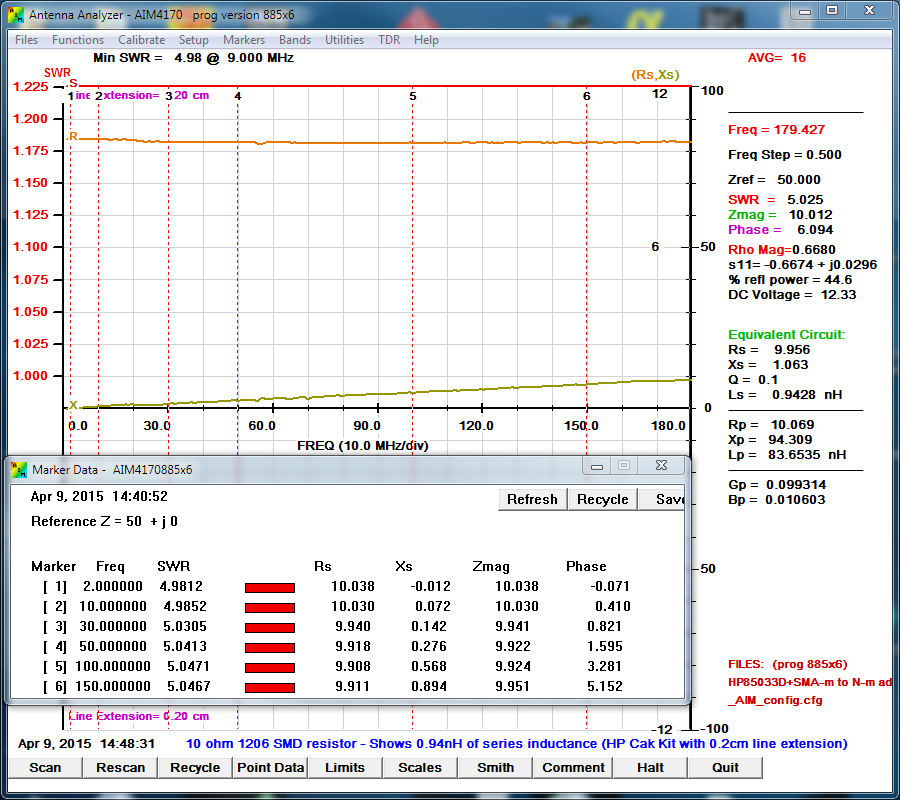
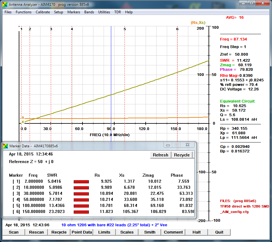
The following capture shows the 10 ohm measurement. The 10 ohm resistor appears to be slightly inductive as the original tests predicted. The equivalent series inductance is 0.94nH.
The following capture shows the 10 ohm measurement. The 10 ohm resistor appears to be slightly inductive as the original tests predicted. The equivalent series inductance is 0.94nH.
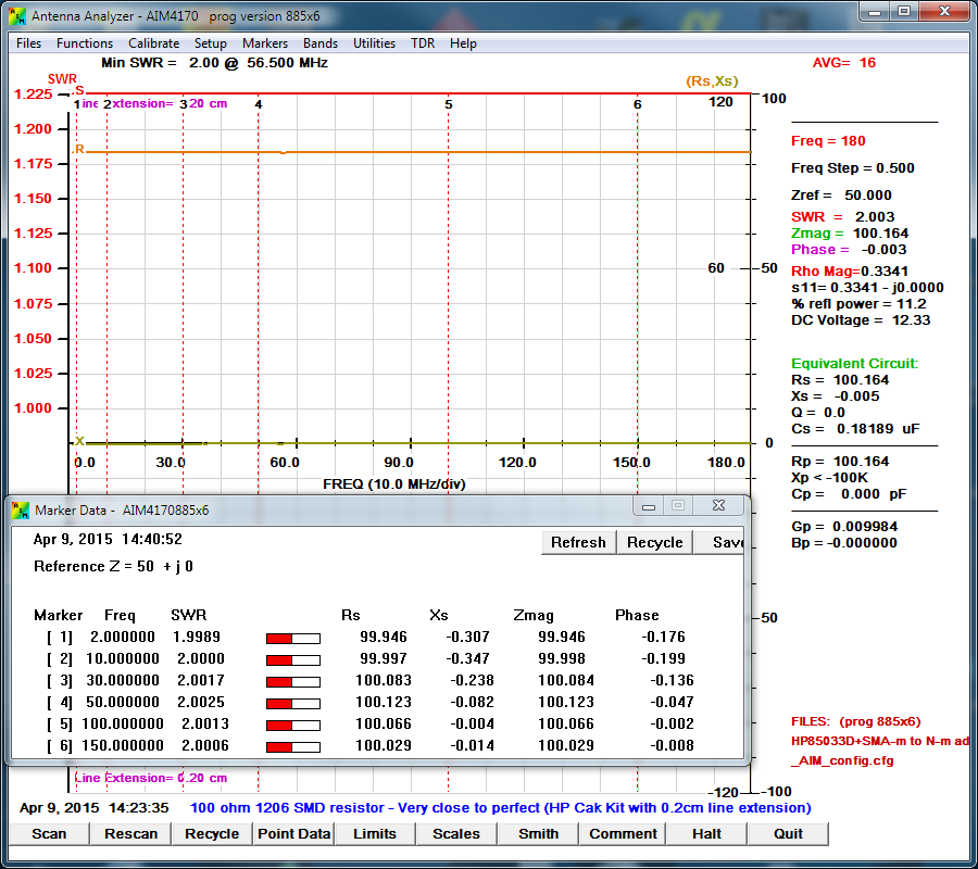
The following capture shows the 100 ohm measurement which is nearly perfect.
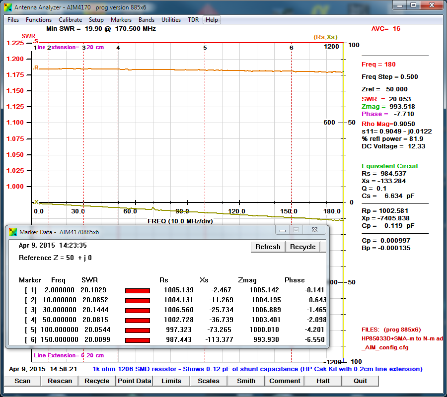
The following capture shows the 1k ohm measurement which is slightly capacitive. The predictions of a shunt capacitance of 0.05pF were measured to be 0.119pF. Measuring the 10k resistor (no graph shown) showed 0.123pF of shunt capacitiance which also exceeded the prediction.
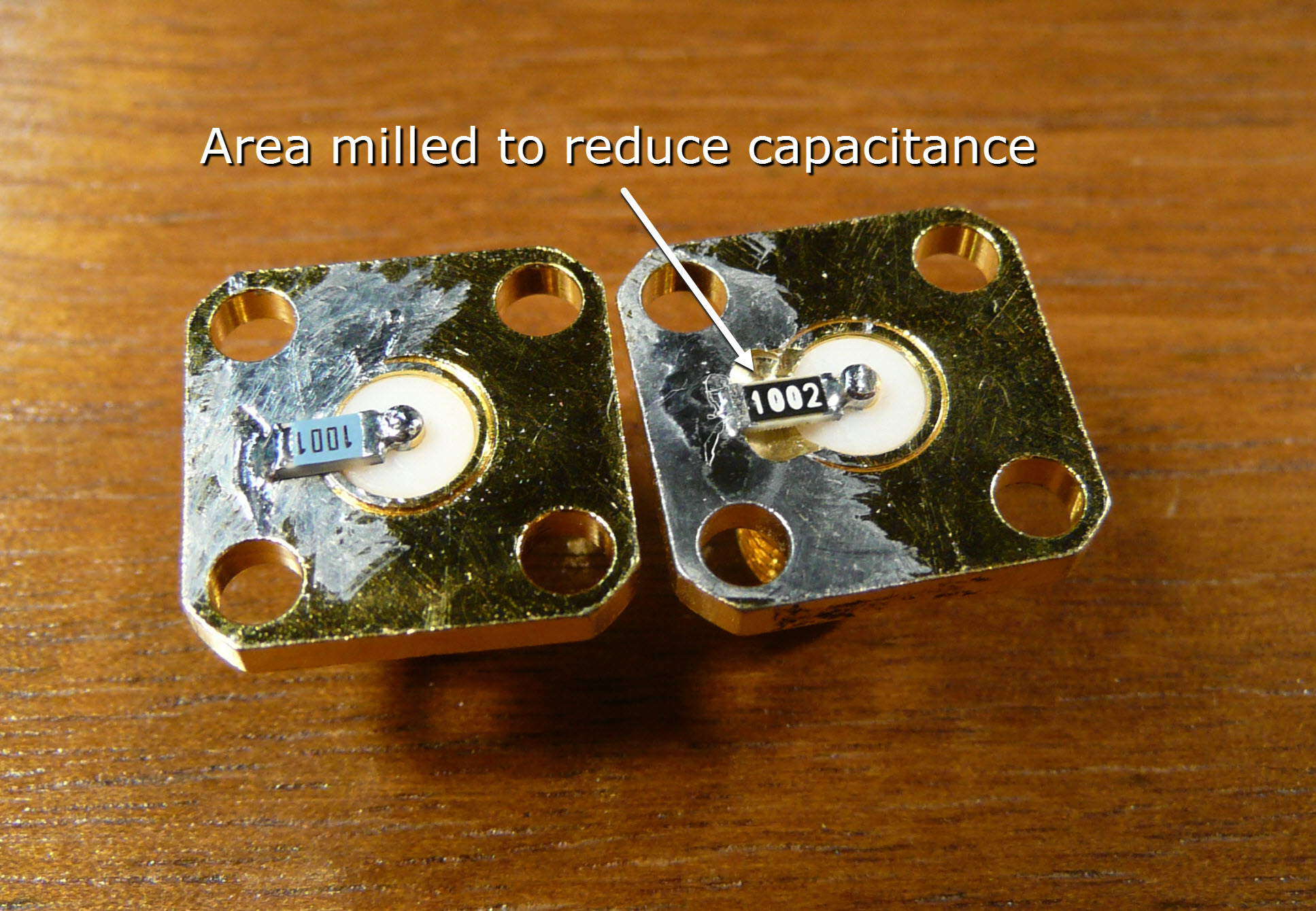
The original prediction had the 1206 SMD resistors mounted at the ends but my test fixture had over 1/2 of the 1206 body against ground increasing the shunt capacitance. The fixture below on the right shows an area milled away from the body of the resistor decreasing the capacitance.
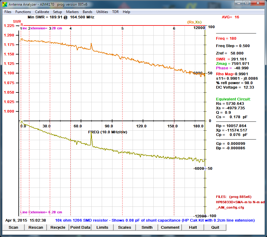
Using the milled fixture and measuring the 10k reisitor now shows shunt capacitance of 0.076pF which seems very reasonable since half the resistor is still is fairly near ground. The fixture could be milled deeper and slightly wider which would help but I'm ready to say this is good enough! At 100MHZ the error in measuring a 10k ohm impedance is slightly over 10%. This is better than the 15-20% I achived when I last made these types of measurements. I must have learned something along the way! As an aside the anomoly at 75MHz is from the DDS in the 4170 and occurs when measuring extremely high impedances.
Making RF impedance measurements in the HF and VHF frequency ranges has become affordable and easy to do but what is the accuracy of these measurements? This is an experiment that will allow anyone to become more proficient at making RF impedance measurements. The need to measure the RF impedance of antennas, transmission lines, components, and circuits is obvious to those doing RF design and experimenting.
Good News
1206 size SMD resistors are inexpensive and can be used (without leads to start) as accurate known impedances to begin the experiment.
There are 3 parts to making reasonable RF impedance measurements:
1.) The inherent accuracy of the the device used to make the measurement.
2.) The calibration of the device and the reference plane where the measurement will be most accurate.
3.) The skill and understanding of the person making the measurement.
I will be using an AIM4170 which has been updated to be equivalent to the current production 4170 D model in terms of accuracy. This is not a test or an endorsement of the 4170 and anyone with any of the competing products can easily do their own tests.
The Challenge
To make RF impedance measurements in the HF and VHF frequency ranges accurately.
Precision resistors of several values can be easily obtained and measured to determine the accuracy of a digital multimeter. Is something similar to this possible when measuring RF impedances up through the VHF spectrum? If these "accurate RF impedances" were inexpensive anyone could spot check their ability to make the measurements and improve their skills.
I did some previous work on making RF high impedance measurements which can be found by clicking here. I concluded that 1206 size surface mount parts are predictable enough to give good results and are large enough that the connection of wires is easily done.
I repeated some of the previous work again by sweeping several resistors from 1 thru 500MHz in a fixture measuring circuit loss and the amplitude rolloff was used to calculate the shunt capacitance of a 1206 size part. This is another method to deduce impedance that is often useful. The assumption is that the shunt capacitance is due to the 1206 package and would be the same for all values of resistance. The 1206 package also has some small series inductance which causes the amplitude to drop at high frequencies for resistances that are small but this effect is generally insignificant compared to the shunt capacitance as the graphs in the previous work showed. The following LTSpice circuit shows a simplified model of the circuit where R3, L1, and C1 are the 1206 part being measured. LTSpice predicts a low frequency loss of 40.1dB and an amplitude increase at 500MHz that is due to the shunt capacitance of the 1206 part.
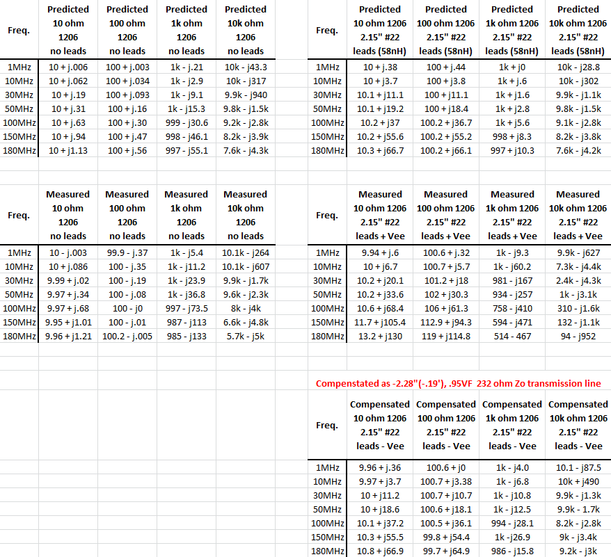
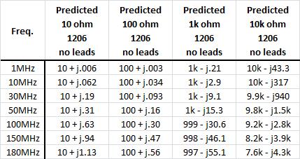
The "predicted values" for the 10, 100, 1k, and 10k ohm resistors at 7 frequencies are shown in the following table and are based on the LTSpice circuit with a parallel capacitance of 0.05pF.
Initial results
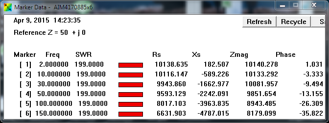
The previous results show that with careful calibration and attention to detail the predicted values of the four 1206 resistors were measured very closely. The 10k ohm resistors which represented a 200:1 SWR were still reasonably accurate.
The previous results show that with careful calibration and attention to detail the predicted values of the four 1206 resistors were measured very closely. The 10k ohm resistors which represented a 200:1 SWR were still reasonably accurate.
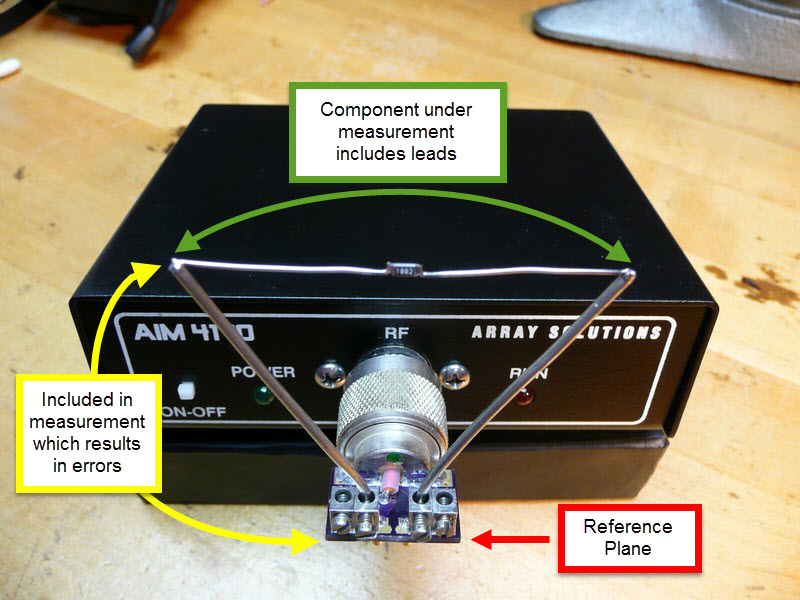
Test with Leaded Components
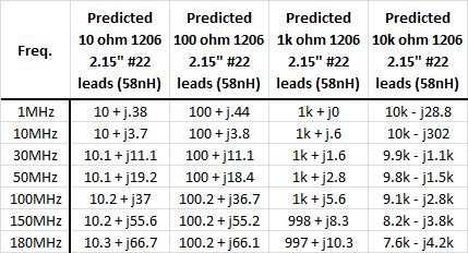
Not all components are small and can be directly soldered to a connector which makes calibrating to a reference plane difficult. The previous four resistors had #22AWG (.0253" or 0.65mm dia.) copper wire soldered to the ends with a total length of 2.2" (2.15" after slodering to large wires) as shown in the following picture. The part now to be measured is the 1206 resistor + the wire leads. Several texts and online calculators predict the leads to add 58nH to the predicted value of the bare resistor.
The homemade adapter was calibrated with bare 1206 SMD parts at the small gold pads between the screw terminals and the large #14 AWG (.064" or 1.63mm did) wires were beyond the reference plane. How badly would this affect the measurements?
Leaded Test Results
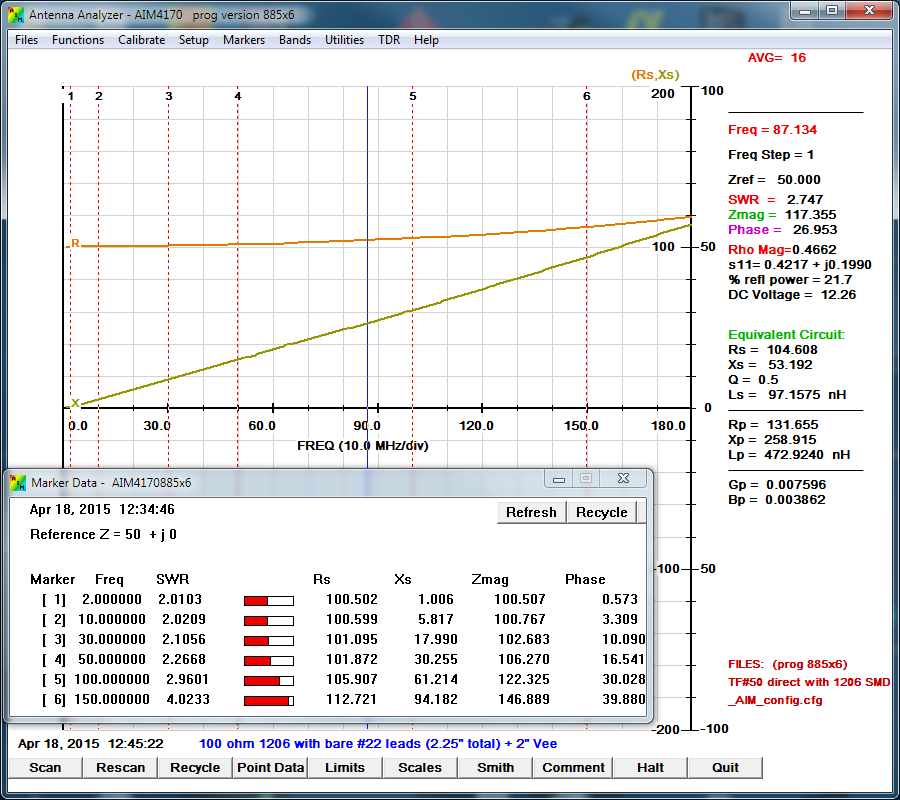
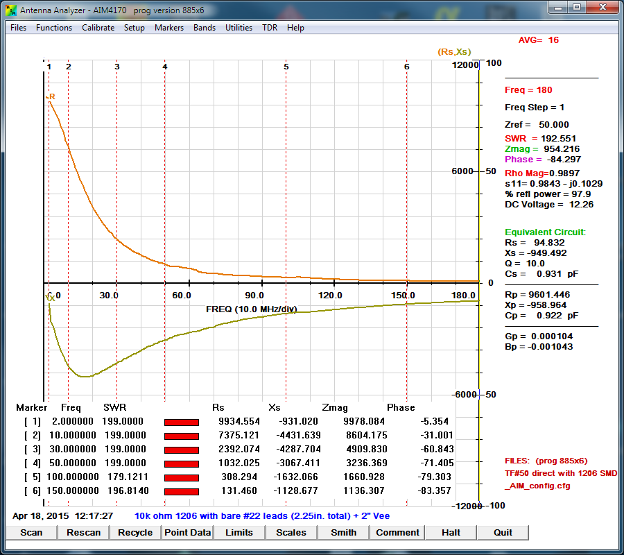
As was done on the previous test the following four graphs show the results. A table of both tests (with and without leads) is shown at the end which is easier to understand than the graphs.
As was done on the previous test the following four graphs show the results. A table of both tests (with and without leads) is shown at the end which is easier to understand than the graphs.
Compensating for the Reference Plane Errors
As can be seen above the reference plane error and the effects of the #14 AWG Vee shaped wires introduced significant errors. The results of the measurements were imported into SimSmith which is a very powerful Smith Chart program that is available at no cost and runs on Windows, Mac, and Linux platforms. It can be downloaded from AE6TY's website which is linked here. SimSmith imports the AIM4170 .csv files and files from other analyzers. Additionally it allows negative component values and negative transmission line lengths which allow the effects of a component to be "undone". I was able to approximate the effects of the Vee which then produced values for the leaded resistors that were very close to what was predicted. The resulting transmission line was -2.28" long with 95%VF, and surge impedance of 232 ohms and this single value corrected all 4 resistor values and some other 1206 size capacitors that I tried.
As can be seen above the reference plane error and the effects of the #14 AWG Vee shaped wires introduced significant errors. The results of the measurements were imported into SimSmith which is a very powerful Smith Chart program that is available at no cost and runs on Windows, Mac, and Linux platforms. It can be downloaded from AE6TY's website which is linked here. SimSmith imports the AIM4170 .csv files and files from other analyzers. Additionally it allows negative component values and negative transmission line lengths which allow the effects of a component to be "undone". I was able to approximate the effects of the Vee which then produced values for the leaded resistors that were very close to what was predicted. The resulting transmission line was -2.28" long with 95%VF, and surge impedance of 232 ohms and this single value corrected all 4 resistor values and some other 1206 size capacitors that I tried.
Results in Table Format
The first column shows the predicted and measured values for the 1206 resistors with NO leads. The second column show the predicted, measured, and reference plane corrected values for the 1206 resistors with leads. The compensation is explained below the table.
The first column shows the predicted and measured values for the 1206 resistors with NO leads. The second column show the predicted, measured, and reference plane corrected values for the 1206 resistors with leads. The compensation is explained below the table.
Conclusion
The tests reported above have been done by a couple of other people with similar results to mine. I also did these tests on another network analyzer with equally good results. These tests allow anyone to determine how well they can measure RF impedances in the HF and VHF spectrum.
The tests reported above have been done by a couple of other people with similar results to mine. I also did these tests on another network analyzer with equally good results. These tests allow anyone to determine how well they can measure RF impedances in the HF and VHF spectrum.