Highpass Filter Design
100W 160m Broadcast Filter
Page content last updated Sep. 15, 2011
Copyright © 2011 Larry Benko, W0QE
I went out to the QTH of Jim Snyder, W0UR to make some impedance measurements on a 160m dipole which was on his tower at a height of 130'. His tower is on a bluff and has an unobstructed view for miles in most directions. I planned on AM broadcast interference so I calibrated my network analyzer through a broadcast filter. I have done this sucessfully in the past. However I was unable to get consistent measurements. A receiver connected to the antenna resulted in the 160m band being filled with intermod, spurious signals, and unidentified junk. I decided to come back later with a spectrum analyzer to see what was going on.
On the next trip with a spectrum analyzer and an external 20dB 2W attenuator the broadcast signals were larger than I believed they would be. The external attenuator was warm to the touch and there were 2 stations with signal levels of ~+27dBm (0.5 Watt), 2 other stations near +15dBm, and several more above 0dBm. No receiver can handle these conditions and I wondered if the transmitted signal might even be affected by these signals. The dipole was being used for receive as well as transmit so the plan was to try to build a high pass filter that could handle a 100W transceiver.
On the next trip with a spectrum analyzer and an external 20dB 2W attenuator the broadcast signals were larger than I believed they would be. The external attenuator was warm to the touch and there were 2 stations with signal levels of ~+27dBm (0.5 Watt), 2 other stations near +15dBm, and several more above 0dBm. No receiver can handle these conditions and I wondered if the transmitted signal might even be affected by these signals. The dipole was being used for receive as well as transmit so the plan was to try to build a high pass filter that could handle a 100W transceiver.

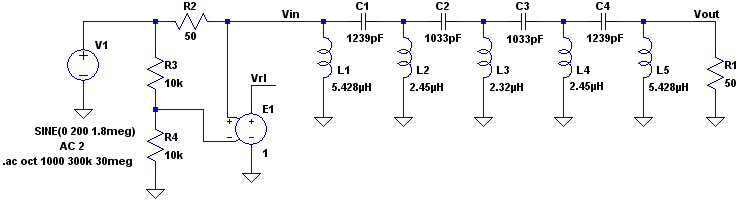
The AM broadcast band extends upward to 1700kHz but in this case the 2 large interfering signals were at 670kHz and 760kHz. However the next 2 largest signals were at 1190kHz and 1490kHz. I decided I wanted a maximum of 0.5dB loss in the 160m band and more than 15dB loss at 1490kHz and more than 60dB at 760kHz. I used the free AADE Filter Design program at http://www.aade.com/filter.htm and came up with a 9th order filter as shown below. The inductor Q's were assumed to be 130. I opted for the 5 inductors topology rather than 5 capacitors in order for the filter to provide static bleed.
The filter consists of the components L1-L5 and C1-C4 and was analyzed in LTSpice which is free and available at http://www.linear.com/designtools/software/. The circuit below has the inductors defined with Q's ~130 and the other components are used to measure input return loss. Also Jim Tonne, W4ENE has a filter design program called ELSIE which is free for 7th order and less or paid for higher order filters which will directly write LTSpice files for analysis. See http://tonnesoftware.com/elsiedownload.html if interested.
The filter consists of the components L1-L5 and C1-C4 and was analyzed in LTSpice which is free and available at http://www.linear.com/designtools/software/. The circuit below has the inductors defined with Q's ~130 and the other components are used to measure input return loss. Also Jim Tonne, W4ENE has a filter design program called ELSIE which is free for 7th order and less or paid for higher order filters which will directly write LTSpice files for analysis. See http://tonnesoftware.com/elsiedownload.html if interested.
The frequency response calculated by LTSpice exactly matches that calculated by AADE Filter Design since both are simulations. At 100W the component stresses are as follows:
L1 = 1.11Arms, L2 = 3.77Arms, L3 = 4.21Arms, L4 = 3.43Arms, L5 = 1.08Arms
C1 = 1.87Arms & 190Vpk, C2 = 2.32Arms & 281Vpk, C3 = 2.20Arms & 267Vpk, C4 = 1.71Arms & 172Vpk
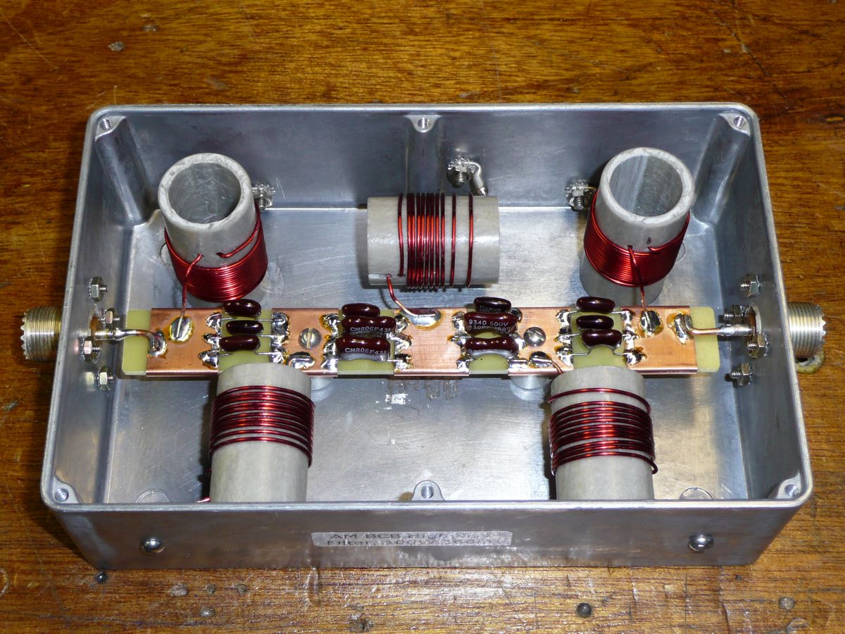
I wound the inductors with #18 enamel wire on 1.0" O.D. fiberglass tubes as can be seen in the pictures below and tried to position them not couple with each other. The values of the inductors were adjusted by tweaking the turn spacing while connected to an inductance meter. A 7.25" x 4.5" x 2.0" diecast aluminum box used was with the SO-239 connectors at either end. The inductors and no other components were initially mounted in the box. A small vector newtork analyzer calibrated through a foot of coax was routed through the holes for the SO-239s and connected to each inductor. This showed that mounting the inductors inside the box reduced the value of inductance a few percent and screwing the lid on the box reduced the inductance an additional few percent. I readjusted the turns spacing and re-measured a couple of times till the inductances were within 1% of the desired values.
Next I made the capacitor strip out of some 0.093" printed circuit board material, measured and mounted the capacitors as shown in the pictures. Each capacitor was made from 3 individual 500V silver mica capacitors to share the current and to get the value within 1% of the desired value. Finally the SO-239s were mounted and the capacitor strip was soldered to the SO-239s and the 5 ungrounded ends of the inductors.
L1 = 1.11Arms, L2 = 3.77Arms, L3 = 4.21Arms, L4 = 3.43Arms, L5 = 1.08Arms
C1 = 1.87Arms & 190Vpk, C2 = 2.32Arms & 281Vpk, C3 = 2.20Arms & 267Vpk, C4 = 1.71Arms & 172Vpk
I wound the inductors with #18 enamel wire on 1.0" O.D. fiberglass tubes as can be seen in the pictures below and tried to position them not couple with each other. The values of the inductors were adjusted by tweaking the turn spacing while connected to an inductance meter. A 7.25" x 4.5" x 2.0" diecast aluminum box used was with the SO-239 connectors at either end. The inductors and no other components were initially mounted in the box. A small vector newtork analyzer calibrated through a foot of coax was routed through the holes for the SO-239s and connected to each inductor. This showed that mounting the inductors inside the box reduced the value of inductance a few percent and screwing the lid on the box reduced the inductance an additional few percent. I readjusted the turns spacing and re-measured a couple of times till the inductances were within 1% of the desired values.
Next I made the capacitor strip out of some 0.093" printed circuit board material, measured and mounted the capacitors as shown in the pictures. Each capacitor was made from 3 individual 500V silver mica capacitors to share the current and to get the value within 1% of the desired value. Finally the SO-239s were mounted and the capacitor strip was soldered to the SO-239s and the 5 ungrounded ends of the inductors.
Click on either picture for higher resolution image
Results
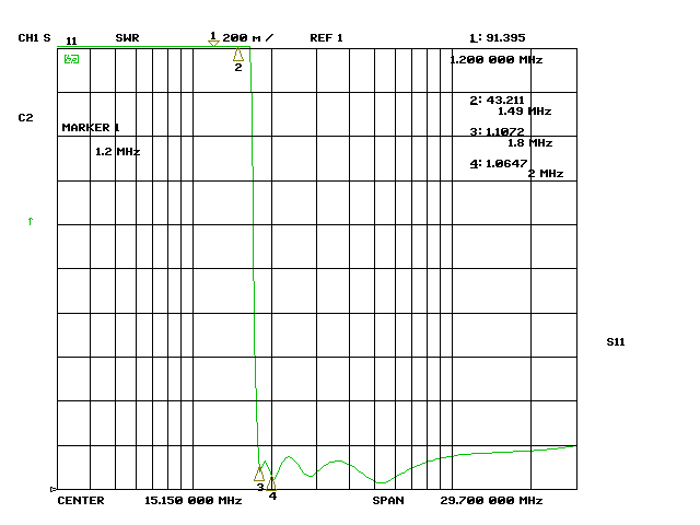
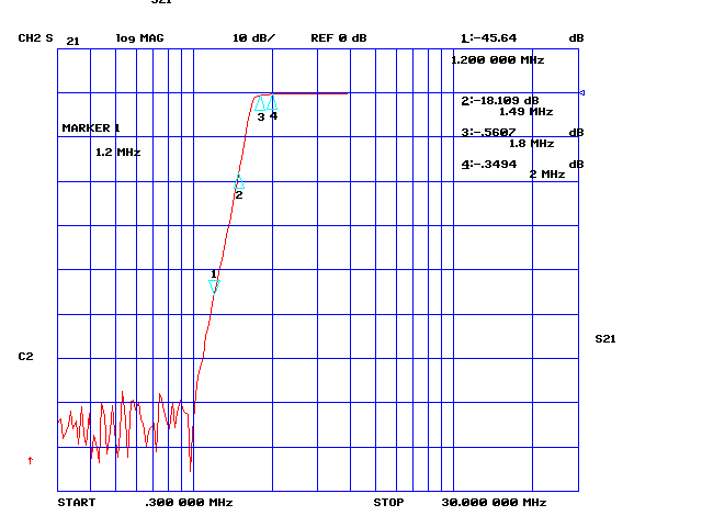
The results were virtually identical to the predicted values. The loss @ 1.8MHz was 0.56dB, 0.31dB @ 2.0MHz, 18.1dB @ 1.49MHz, 45.6dB @ 1.20MHz and >70dB @ 760kHz. Input SWR was 1.1:1 or better on 160m and less than 1.2:1 on all other HF bands. Applying 100W continuous carrier for 2 minutes produced minimal warming in inductors L2, L3, and L4. Increasing the power to 200W still resulted in acceptable inductor temperatures. In retrospect I would should have used #16 wire for L2 through L4 which have higher current than L1 and L5.
Finally installing the filter at W0UR's resulted in a total elimination of the intermod and spurious signals with any receiver. I don't know if the transmitter output might have been affected without the filter but with the filter this is no longer a question.
Finally installing the filter at W0UR's resulted in a total elimination of the intermod and spurious signals with any receiver. I don't know if the transmitter output might have been affected without the filter but with the filter this is no longer a question.