RF Clipper
Receiver Protector
In my quest to have a spectrum based tool to track down RF interference (RFI), I built an active monopole amplifier which was capable of outputting a signal that potentially might damage some software defined radios (SDR) if I happened to inadvertently drive by a location such as an AM radio station. The active monopole amplifier project can be seen by clicking here.
I have used simple diode shunt circuits in the past but always wondered what the performance of the circuit was. The final circuit shown below was analyzed similarly to how I measured the performance of the active monopole amplifier.
I have used simple diode shunt circuits in the past but always wondered what the performance of the circuit was. The final circuit shown below was analyzed similarly to how I measured the performance of the active monopole amplifier.
Performance of a Simple Diode Clipper
My Perseus SDR has a 50 ohm antenna input and begins clipping at an input signal of -2dBm (.281Vrms or .398Vpk). I know from experience that the radio withstands a +10dBm (.707Vrms or 1.00Vpk) signal. Initially I built a circuit with a single 5 ohm series resistor and a back to back diode pair to ground. I tried a few diode types and ended up with BAV-99 diodes which are used by the billions in equipment for electrostatic dishcharge (ESD) protection. These are ultra fast silicon (not Schottky) diodes with a shunt capacitance of ~1.5pF with 2 diodes in a SOT-23 package. They are capable of handling 200mA continuous and can take 1A for 1 second or 8A for 300us. I also had a reel of 5000 on hand so I could easily blow up several.
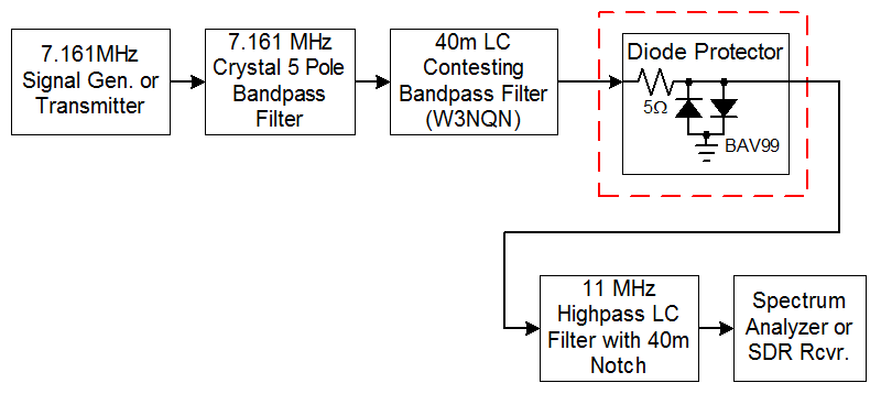
I used the same circuit (shown below) as I did for the active monopole antenna project to determine the performance. The 7MHz generator frequency was cleaned up by the 5 pole 3kHz wide crystal filter which was followed by the 40m bandpass filter creating a 7.161MHz signal with harmonics that were down >120dB. The 11MHz highpass wilter with a 40m notch reduced the fundamental signal by more than 60dB so that I could measure the harmonics accurately.
I used the same circuit (shown below) as I did for the active monopole antenna project to determine the performance. The 7MHz generator frequency was cleaned up by the 5 pole 3kHz wide crystal filter which was followed by the 40m bandpass filter creating a 7.161MHz signal with harmonics that were down >120dB. The 11MHz highpass wilter with a 40m notch reduced the fundamental signal by more than 60dB so that I could measure the harmonics accurately.
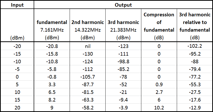
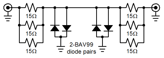
After making preliminary measurements I decided to build the protector with 5 ohm resistors on both ends as shown in the schematic at he top of the page. I also doubled up the diodes for the test as shown in the schematic. I intended to put the clipper in a small tube with BNC connectors on both ends and wanted to be able to plug in the clipper in either direction. The table below shows the performance with 5 ohm resistors on both ends. The circuit has a 0.83dB loss in a 50 ohm circuit and slightly increases the SWR to 1.2:1. The frequency is very flat over the HF range and down 0.2dB at 200MHz.
For my intended use of the clipper at levels less than 0dBm the performance is quite good. The 2nd harmonic suppression is extremely good due to using matched diodes in the BAV-99 diode pair. The 3rd harmonic suppression of of -77dB is slightly worse than the performance of the active monopole amplifier but is still very good. Note how the maximum clipping level keeps the fundamental frequency below the desired +10dBm. If two BAV-99 diodes were added in series the performance values would increase 6dB since all the voltages would be doubled. Also the shunt capacitance would be halved.
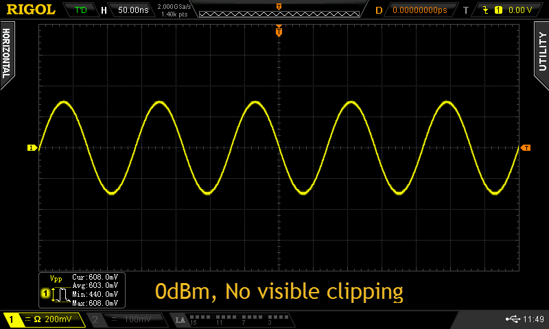
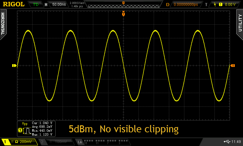
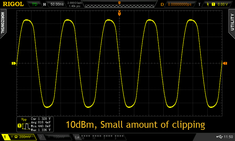
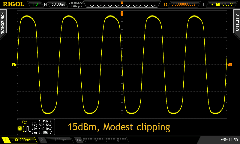
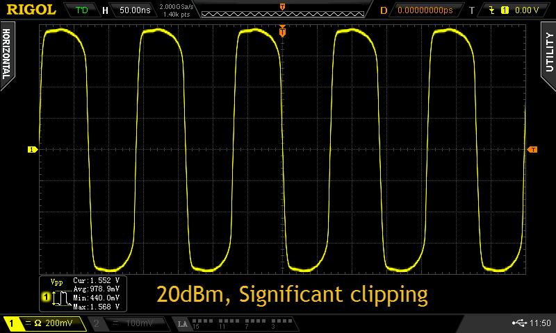
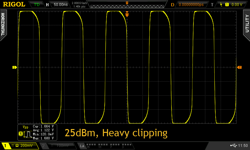
Below are scope captures of the clipper output at various input levels.
Below are scope captures of the clipper output at various input levels.
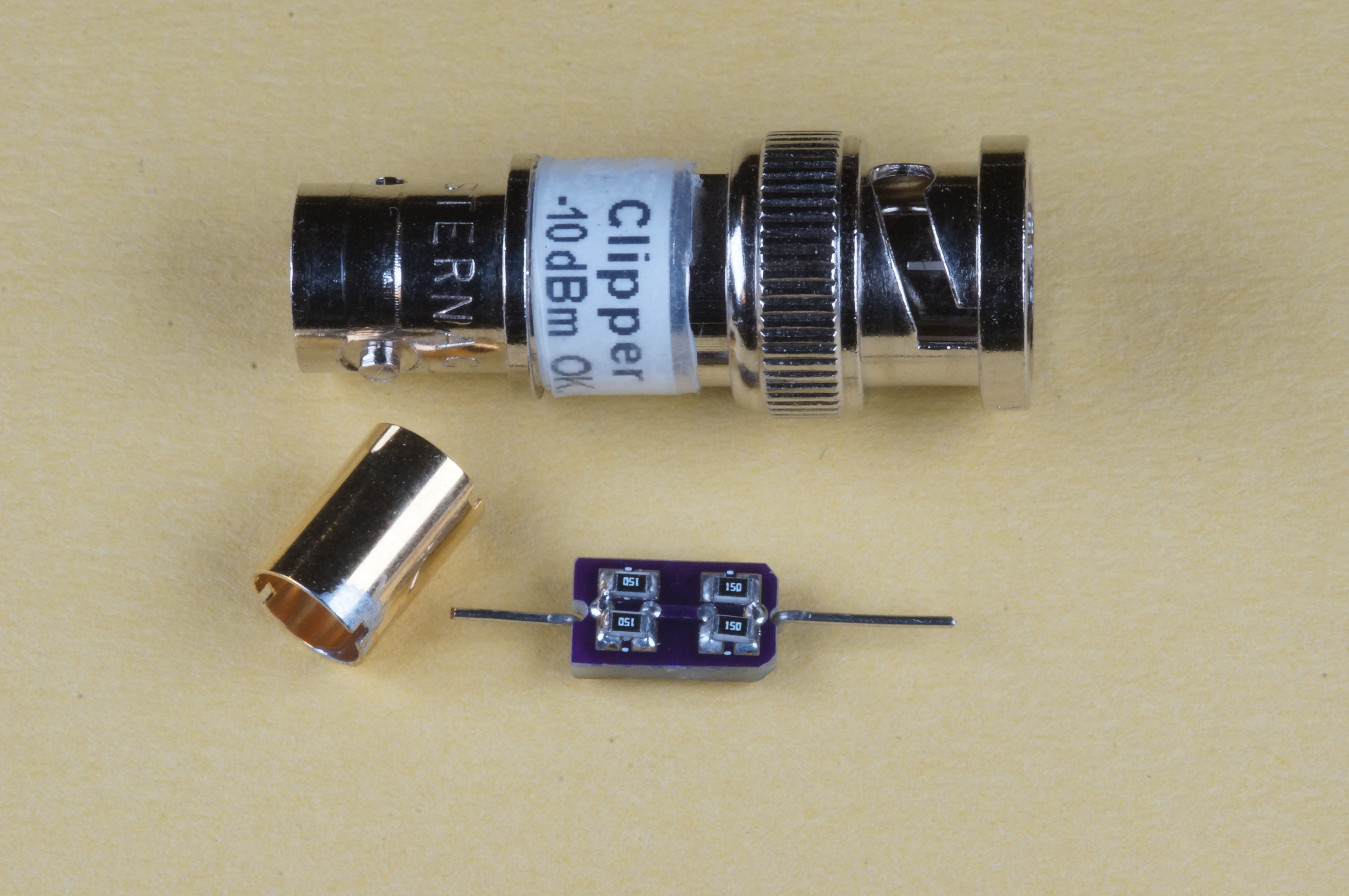
The final circuit is comprised of six 15 ohm 0805 thick film resistors which are Panasonic ERJ type and rated for surge use and rated at 0.5W each. By using these resistors and doubling up the diodes the clipper can withstand continuous input levels of 2W (+33dBm). I tested brief periods of about 1 second at 5W without any damage. At 5W the clipper limited the output to +/ 1.20Vpk.
The resistors and diodes can be obtained from Digikey (www.digikey.com).
Resistors: Digikey# P15ADCT-ND (Panasonic 667-ERJ-P06J150V) $.11 each ($.053ea for 100).
Diodes: Digikey# BAV99FSCT-ND (Fairchild/ONSemi BAV-99) $.21 each ($.09ea for 100).
The resistors and diodes can be obtained from Digikey (www.digikey.com).
Resistors: Digikey# P15ADCT-ND (Panasonic 667-ERJ-P06J150V) $.11 each ($.053ea for 100).
Diodes: Digikey# BAV99FSCT-ND (Fairchild/ONSemi BAV-99) $.21 each ($.09ea for 100).
Final Product
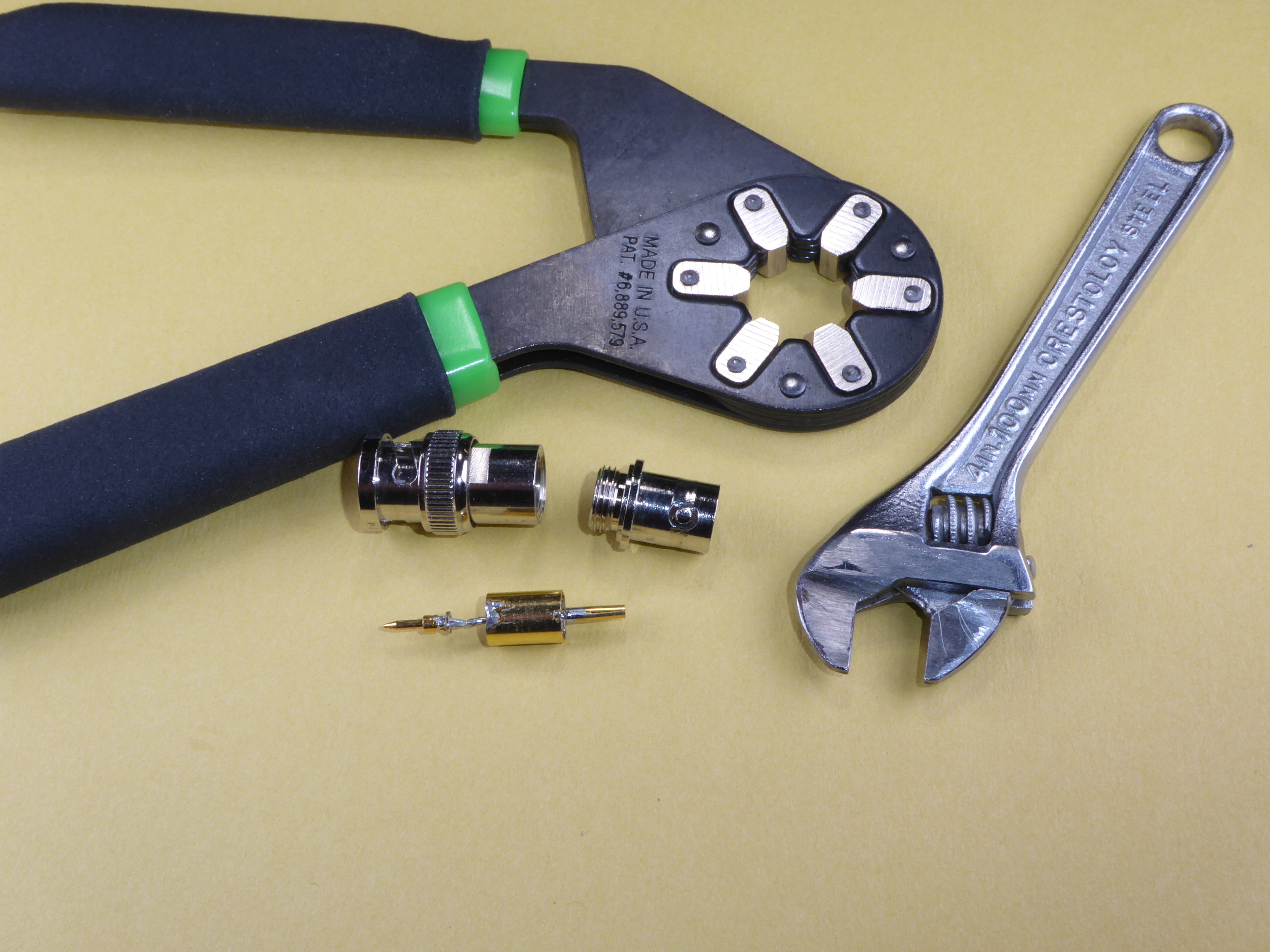
The clipper could be added inside an SDR in which case I would only use a single 5 ohm resistor on the antenna side. I chose to build the clipper in a re-purposed RF attenuator package that had BNC male and female connectors on the ends. I picked up a large number of these RF attenuators for about $.50 each from a company that was relocating. At the time I didn't realize that these attenuators were easy to unscrew and I could put my own circuits in them. Shown below are the attenuators and a tool that is available from many hardware stores that clamps circular shapes without damage. Also shown is the tiny circuit board I had made to put the circuit inside the brass tube. The are many other ways to protect your SDR. You need to be careful when driving around that there might be some incredibly strong signals that you might not be aware of.
If these clipping levels are too low for your intended use the number of diodes can be increased. Adding diodes so that there are 2 diodes in series will increase the clipping levels by a factor of 2 in voltage or 6dB. Incresing to 3 diodes in series would increase the clipping levels an additional 3.5dB or a total of 9.5dB. Remember that in my case I was using a short vertical which has a lower antenna factor than a full size antenna so for me 1 diode drop to ground was perfect..
If these clipping levels are too low for your intended use the number of diodes can be increased. Adding diodes so that there are 2 diodes in series will increase the clipping levels by a factor of 2 in voltage or 6dB. Incresing to 3 diodes in series would increase the clipping levels an additional 3.5dB or a total of 9.5dB. Remember that in my case I was using a short vertical which has a lower antenna factor than a full size antenna so for me 1 diode drop to ground was perfect..
Page content last updated Feb. 8, 2017
Copyright © 2017 Larry Benko, W0QE

IMD Measurements
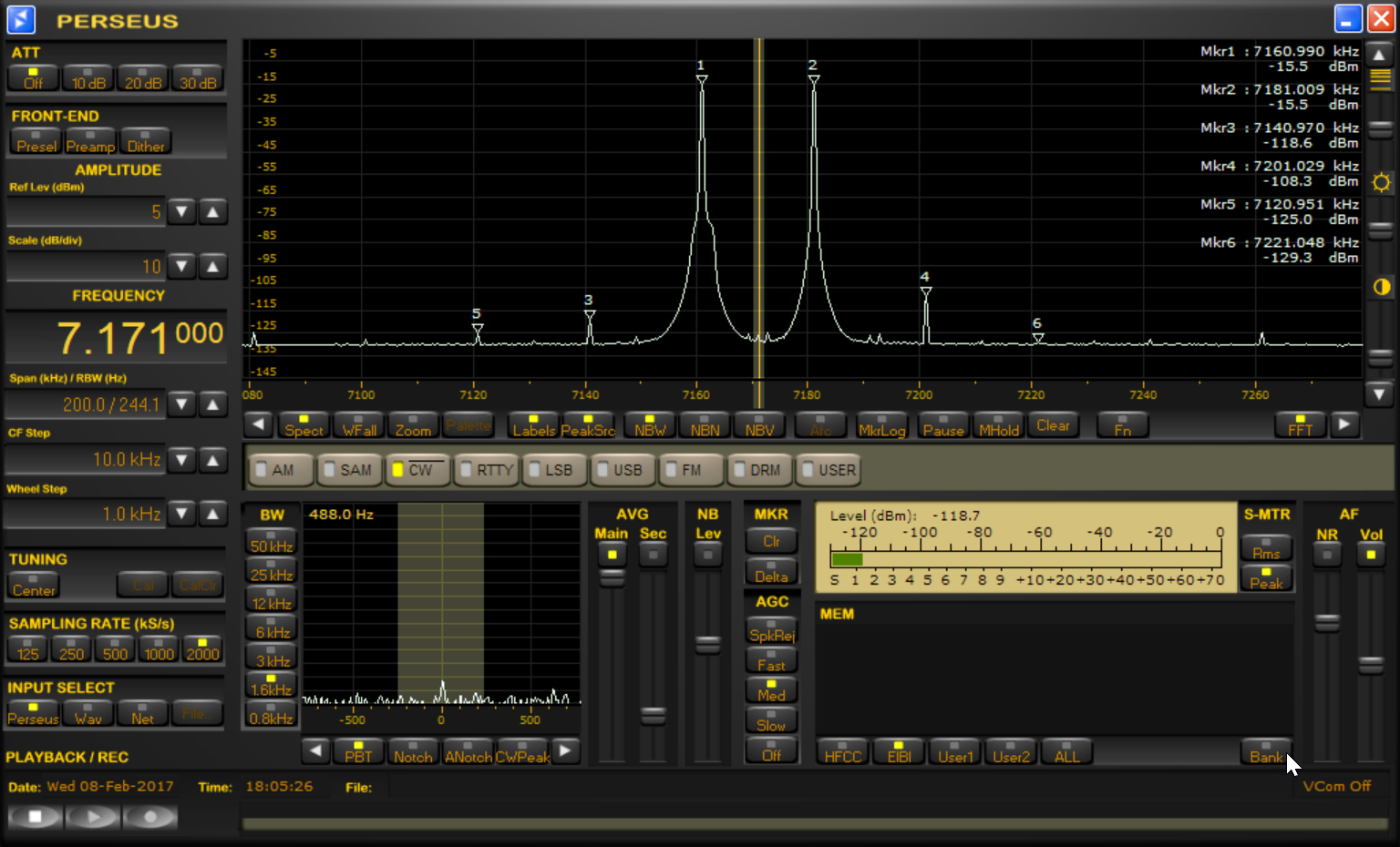
A few people asked me why I didn't make IMD measurements instead of the harmonic measurements. The answer is that it isn't that easy to measure IMD levels of 100dB. However with a little effort I was able to make the measurements as shown below. The 2 carriers are at 7.161MHz and 7.181MHz and shown are the IMD3 through the IMD9 products.
The graph below was done with 2 carriers that were each -10.5dBm which means the peak voltage is equivalent to a -4.5dBm single frequency. This was about 1dB below where the Perseus indicated that clipping was occurring. In this case the worst case IMD is 91.5dB. I also made thes measurements on an 8560EC spectrum analyzer which gave an answer of -85dB but I believe I was at the limits of the analyzer.
The graph below was done with 2 carriers that were each -10.5dBm which means the peak voltage is equivalent to a -4.5dBm single frequency. This was about 1dB below where the Perseus indicated that clipping was occurring. In this case the worst case IMD is 91.5dB. I also made thes measurements on an 8560EC spectrum analyzer which gave an answer of -85dB but I believe I was at the limits of the analyzer.
This graph shows the IMD for the 2 frequencies that were each -15.5dBm which means the peak voltage was about 6dB below where the Perseus would clip. In this case the worst case IMD is 92.8dB.