Page content last updated Mar. 27, 2014
Copyright © 2014 Larry Benko, W0QE
Small RFI Generator
Why Would You Want an RFI Generator?
RF Interference for those of us who use the RF spectrum is an ever present problem. Inadvertant radiators (computers, power lines, appliances, switching power supplies, "green" lighting, grow lights, plasma TVs, etc.) can produce RF energy which interferes with devices (receivers) intended to receive RF energy.
The need to track down these sources of RF interference requires a competency that is not obtained by reading a book or participating in an internet interest group. It requires some modest equipment which is usually a loop antenna, a receiver with a signal strength indicator, and a lot of practice to be really competent.
The need to track down these sources of RF interference requires a competency that is not obtained by reading a book or participating in an internet interest group. It requires some modest equipment which is usually a loop antenna, a receiver with a signal strength indicator, and a lot of practice to be really competent.
Click on picture for higher resolution image
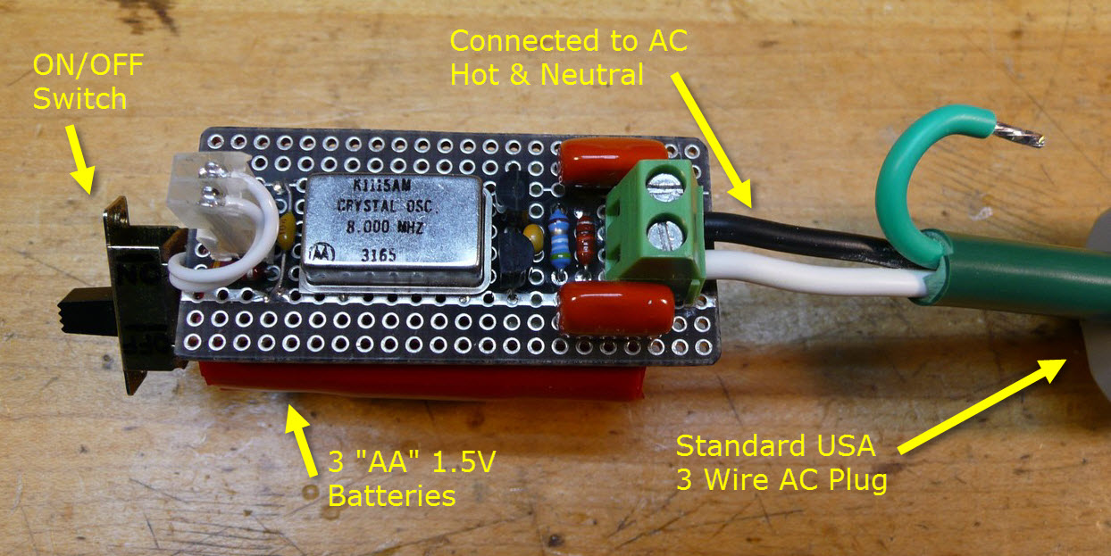
I have built several of these RFI generators at frequencies from 3MHz to 148MHz (9th harmonics of 16.384MHz = 147.456MHz). The odd harmonics are very strong and usable but the even harmonics are much weaker since the output is a square wave. The schematic of the device pictured above is shown below.
The RFI generator can be connected in several ways which represent how devices produce RFI:
1.) Connect each screw terminal to a piece of wire 5 to 20 ft. long will generate an easily heard signal but this is not what the generator was designed for.
2.) Connect the screw terminals to the AC hot and neutral wires (black = hot & white = neutral). This is the classic differential current RFI. At my QTH this produced an S9+25dB signal. Myths about differential currents not radiating are false. The differential current gets partially converted to common mode current when the line is not balanced. The AC wiring is a very good example since the hot wire is switched and the neutral and ground wires are not creating a very unbalanced transmission line.
3.) Connect the screw terminals to the AC hot and ground wires (green = ground). At my QTH this produced an S9+28dB signal.
4.) Connect the screw terminals to the AC ground and an external 6-10 ft. pigtail connected to nothing. This is the similar to many types of common mode current that occurs. At my QTH this produced an S9+32dB signal.
5.) Connect the screw terminals to 8 to 10 turns of wire wound around a #43 split toroid. Then the toroid can be clamped on a wire and the RFI signal will be coupled into that wire.
6.) The signal was barely S1 if nothing is connected to the terminals indicating that the generator acts like a point source.
The most common forms of interference emanate from AC power lines either from the local utility company or from devices connected to electrical wiring in homes and businesses. A simple device that could easily mimic these types of interference for use as practice should be valuable. Most RF interference generally occurs over a broad frequency range but since interference is tracked at some specific frequency this test generator only needs to operate at a single frequency which allows for generation of a very strong frequency and still be powered from small batteries.
The device shown in the picture below is built around a common CMOS oscillator package which produces a fast rise time square wave and is powerful enough to generate S9+30dB noise at my QTH. These oscillators can be purchased from companies such as Digikey or Mouser, cost about $2, and come in a large number of frequencies. They are available in surface mount or DIP 8 or 14 pin packages and operate on all logic standard voltages. The most useful ones are 5V and 3.3V ones in either 8pin or 14 pin DIP packages which can be powered from 3 or 2 "AA" or "AAA" batteries respectively and do not need a voltage regulator.
The device shown in the picture below is built around a common CMOS oscillator package which produces a fast rise time square wave and is powerful enough to generate S9+30dB noise at my QTH. These oscillators can be purchased from companies such as Digikey or Mouser, cost about $2, and come in a large number of frequencies. They are available in surface mount or DIP 8 or 14 pin packages and operate on all logic standard voltages. The most useful ones are 5V and 3.3V ones in either 8pin or 14 pin DIP packages which can be powered from 3 or 2 "AA" or "AAA" batteries respectively and do not need a voltage regulator.
Circuit Description
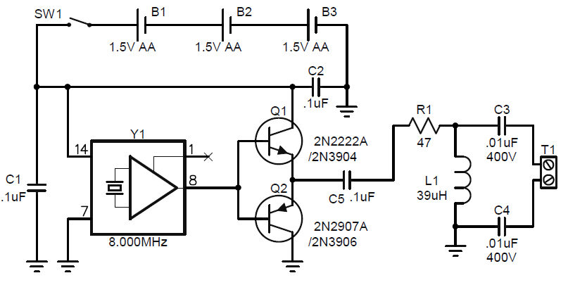
The RF generator above was built with a 5V (runs fine from less than 4V to 6V) 8.000MHz CMOS oscillator which I had on hand. I used this frequency since RF interference between 40m and 20m is very common. Therefore I used 3 batteries in series to power the 5V oscillator. Some oscillators have a chip enable or output enable pin which may need to be connected to either the positive voltage or ground (my oscillator did not have this feature so pin 1 was left open). The oscillator draws about 20mA so a small ON/OFF switch was used. Transistors Q1 and Q2 are just a follower circuit and are not really required but help to protect the oscillator at the initial time the circuit is plugged into an AC outlet. As shown above capacitors C3 and C4 are either class X 250VAC types or 400V DC. C3, C4, and L1 form a filter to keep the 120VAC out of the oscillator. L1 is a 1/4W resistor sized part with a self resonant frequency above 50MHz and the value is not critical. C5 blocks the DC from the square wave and R1 helps to protect the oscillator. If Q1 and Q2 are omitted, directly connect the oscillator output to C5 and increase R1 to around 200 ohms. I taped the 3 batteries together and connected the small circuit board to the batteries with double sided sticky tape. Connections to the batteries were directly soldered to the batteries (be quick when soldering) and I am still on the original set of batteries which should last about 60 hours which is a LOT of practice.
How to Use the Generator
Make connections to the AC power cord BEFORE connecting the plug to the AC outlet.
Connection #5 above can be used to couple an RF current onto the ground wire that comes down from every
power pole. The ground wire is in parallel with the ground wires on every other power pole but the distance
between poles makes for a good antenna. The ground wire is stapled to the pole but at the very bottom it
spreads away from the pole to go to the ground rod and is easy to snap on the split toroid. This signal can be
heard for a thousand feet. A accomplished tracker can find the actual pole of the signal.
Repeat, be careful of the AC line voltage!
Start by using connection #2, #3, or #4 above and have someone plug the device into an AC outlet in your own
home. If you can't find the device in 5 minutes you need more practice.