Coupling Between Coils
or Coefficient of Coupling (Leakage Inductance)
Coupling Between Coils
Page content last updated Jun. 16, 2012
Copyright © 2012 Larry Benko, W0QE
The above drawing is from Wikimedia Commons which has granted permission to copy, distribute and/or modify it under the terms of the GNU Free Documentation License, Version 1.2 or any later version published by the Free Software Foundation.
Measuring Coefficient of Coupling
Inductance is the property of a component (called an inductor) where a change in current induces a voltage in the component (self inductance) and in nearby components (mutual inductance). Any two nearby inductors have some small amount of coupling and no two inductors have 100% coupling. Any coupling which is less than 100% will produce some leakage inductance so coefficient of coupling and leakage inductance are closely related. For a more in depth explanation see either the English version of Wikipedia or the All Language version of Wikipedia and search for leakage inductance, inductance, mutual inductance etc.
The drawing below shows a 2 winding transformer where some fraction of the inductance couples perfectly to the same fraction of the second winding (which may be a different overall inductance). In reality some fraction of the flux produced by every turn in the winding couples with the second winding but the model accurately gives the correct results and is easier to analyze.
The drawing below shows a 2 winding transformer where some fraction of the inductance couples perfectly to the same fraction of the second winding (which may be a different overall inductance). In reality some fraction of the flux produced by every turn in the winding couples with the second winding but the model accurately gives the correct results and is easier to analyze.
There are 2 ways to measure the coefficient of coupling between 2 inductors and both yielded similar results for moderate values of the coefficient of coupling (k). However depending on whether k is near 0 or 1 will determine which method is easier and more accurate.
Method#1:
Refer to the drawing above and apply a voltage across one inductor and measure the open circuit voltage across the second inductor. The source voltage must be a low impedance and the measurement voltage made at high impedance. Either inductor can be driven with the other one measured and the resulting value of k was virtually the same. V1 and V2 are the inductor voltages and L1 and L2 are the inductances with nothing else connected to the inductors. The square root of the ratio of inductances is the turns ratio and k accounts for the fact that not all the flux is coupled.
Then: V2 = V1*k*sqrt(L2/L1) or V1 = V2*k*sqrt(L1/L2)
Method#2:
Measure the inductance of one inductor with the other inductor not connected to anything. Then measure the inductance of the same inductor with terminals of the other inductor shorted (Lsc). Again the measurement can be made in either direction.
Then: Lsc1 = (1-k2)*L1 or Lsc2 = (1-k2)*L2
However if the coefficient of coupling is 0.05 method #2 requires the accurate measurement of 2 inductances which are 0.25% apart which is quite difficult. Consequently I ended up using method #1 but used my HP 8753B vector network analyzer (VNA) with 50 ohm source and load impedances so the formula needed correcting due to the finite source and load impedances. Choking the coax cables to the inductors produced more predictable results when flipping an inductor 180 degrees (which should not affect the coefficient of coupling). I used 3 and 1/2 turns (1 turn is 1 pass thru both cores) of RG-316 thru 2 side by side #31 material cores which resulted in choking impedances of 1k ohm @ 1.6 MHz rising to >3k ohms from 4 to 30MHz, and >2k ohms at 50 MHz. Then I wrote a conversion program to calculate k from S21 measured by the VNA. The calculated coefficient of coupling was now somewhat dependent on frequency and the inductance which was expected due to the loading but any values of S21 less than -65dB amounted to insignificant coupling and were still 25dB above the noise floor of my VNA.
Reason for this Page
This page shows data I measured in conjunction with building a high power solid state amplifier. The low pass filters required for the amplifier are designed assuming all inductors in the filter do NOT couple with each other. Coupling changes the filter response in a generally undesirable way. Using free software such as LTSpice a filter can easily be analyzed with any amount of coupling between the inductors in the filter, but LTSpice needs the coefficient of coupling between each inductor pair to do the analysis.
The problem was to determine what kind of coupling exists between various types of commonly used inductors. I was unable to find previous studies, which I'm sure have been done, so I decided to do some experiments which are presented below. I thought others might find this data interesting. Several different inductor types and spacings with the measured coefficient of coupling are shown at 4 different frequencies from 2MHz thru 50MHz.
The problem was to determine what kind of coupling exists between various types of commonly used inductors. I was unable to find previous studies, which I'm sure have been done, so I decided to do some experiments which are presented below. I thought others might find this data interesting. Several different inductor types and spacings with the measured coefficient of coupling are shown at 4 different frequencies from 2MHz thru 50MHz.
Small UL Class 2 transformers in the USA use leakage inductance to limit short circuit current without excessive heating while large power grid 50/60Hz transformers are designed with the absolute minimum leakage inductance for good voltage regulation. At RF frequencies leakage inductance causes power splitters/combiners to have reduced bandwidth and need capacitive compensation. RF filters may not yield the desired shape and impedance if inductors couple unexpectedly.
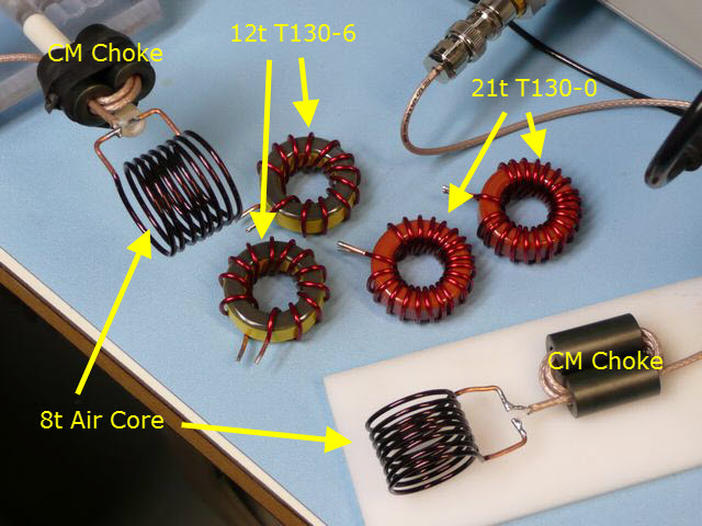
The picture above shows the 2 common mode chokes connected close to the air wound coils with the other 4 coils not connected. All tests were done with like pairs of inductors.
#1) 8 turns #14 Copper wire air core, 1.1"OD x 0.95" length, measured 1.32uH (1st resonance @ 130MHz).
#2) 12 turns #14 Copper wire T130-6 core u=6 (Yellow/Brown), measured 1.55uH (1st resonance @ 93MHz).
#3) 21 turns #14 Copper wire T130-0 core u=1 (Reddish Brown), measured 0.78uH (1st resonance @ 170MHz).
These cores look similar to the red #2 (u=10) cores but are browner and weigh less (phenolic core).
All the inductors were approximately the same size and all had good Q. The T130-0 inductors are essentially air wound (u=1) except that the toroidal shape is expected to couple less than a conventional cylindrical air core inductor. The inductance values are similar to values that would be used at HF.
Results
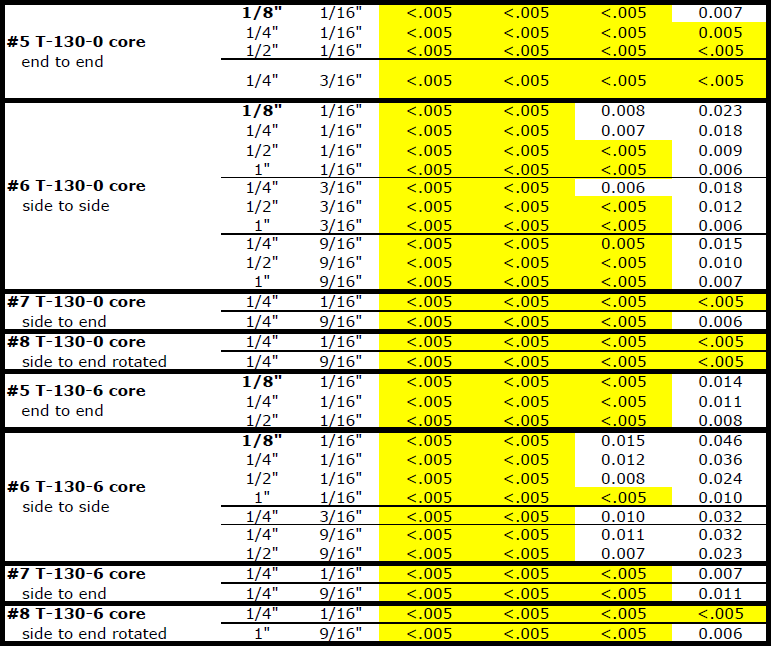
Conclusions
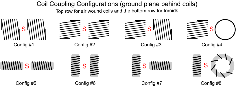
Not shown in the above data is the polarity of the coupling. In the unloaded output case the output voltage will be exactly in phase or out of phase with the source voltage. In schematics this is shown as phase dots on the coils. Any phase shift between input and output voltages is due to leakage inductance, capacitance between the inductors and a finite load impedance. In order to determine the effects of coupling between inductors in a filter both coil polarities must be simulated as they will have different effects. The polarity is obvious in some configurations such as "end to end" and "side to side" for the air core inductors. The air core "side to end" configuration tries to reduce the net flux to zero which obviously does not happen completely and the resulting coupling may be either polarity.
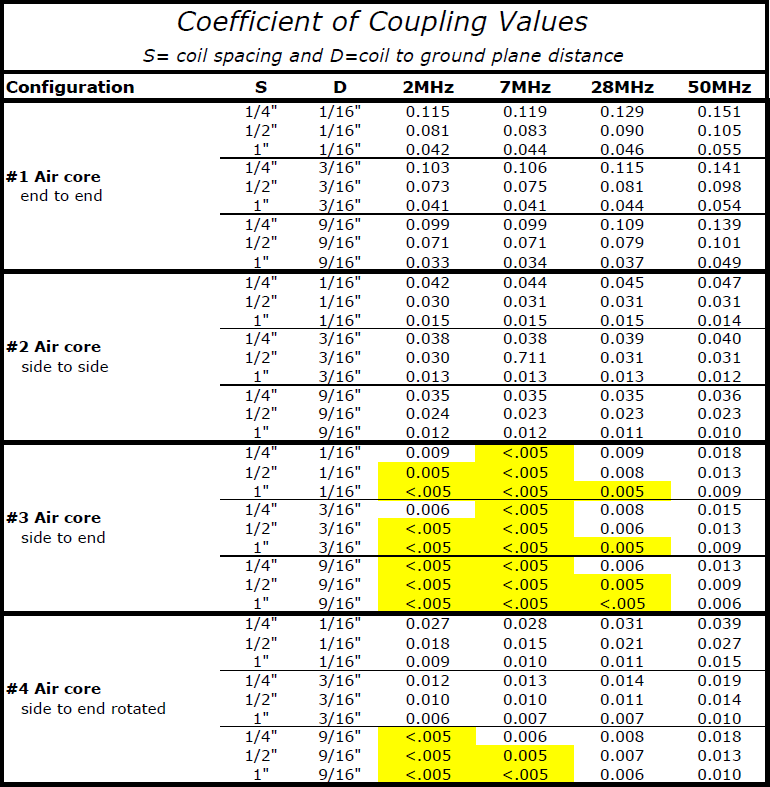
Simulations show that Butterworth and Chebyshev filter topologies behave within a couple of dB to the predicted values in the stopband when the coefficient of coupling between adjacent inductors is less than .005 which is why I highlighted the values in the above table for k <= .005. Filter types such as Cauer (Elliptic) show significant frequency changes in the stopband nulls for coefficient of couplings of .005 which necessitates slight changes in the capacitors across the inductors. The more agressive filter types such as the Cauer are more sensitive to component values in general which need to be considered.
The tests were all done in the presence of a ground plane which was not connected to the inductors. The distances to ground of 1/16", 3/16", and 9/16" equate to the inductors being mounted on the top side of a 1/16" thick printed circuit board (PCB) with the height above the PCB being 0", 1/8", or 1/2" and the bottom of the PCB being the ground plane. The distances between the inductors were the air gap distances and not the distances from the cores.
The tests were all done in the presence of a ground plane which was not connected to the inductors. The distances to ground of 1/16", 3/16", and 9/16" equate to the inductors being mounted on the top side of a 1/16" thick printed circuit board (PCB) with the height above the PCB being 0", 1/8", or 1/2" and the bottom of the PCB being the ground plane. The distances between the inductors were the air gap distances and not the distances from the cores.
Tests
For nicely behaved filters such as Butterworth and Chebyshev with Ap < 0.1dB coefficients of coupling between the inductors of .005 or less change the stopband loss less than 1 dB from no coupling. The passband is affected much less for coupling between the inductors. Click here (you might want to right click and save) to download an LTSpice file (LTSpice files are text files) showing the filter response of a 5th order Chebyshev 20m lowpass filter with various coefficients of coupling in both polarities. Cauer (elliptic) filters are much more sensitive to coupling between the inductors and couplings as low as .001 might require small changes in the capacitors across the inductors.