Page content last updated Sep. 7, 2011 (orig. content May 13, 2008)
Copyright © 2008-2011 Larry Benko, W0QE
Click on any pic for higher resolution image
All the air core inductors are 8 turns wound on a 0.95" diameter form on a lathe resulting in a 1.00" inside diameter when removed from the form and are about 1.5" long. The length was adjusted slightly to produce an inductance of 1.00uH +/- 3%.
#1) #10 (0.100" diameter) bare shiny copper wire
#2) #10 bare copper wire that has been outside for
3 years in Colorado
#3) #10 bare copper wire heavily treated with
Selenium dioxide resulting in a black Copper (II)
Oxide (CuO) finish
#4) 0.093" copper tubing from an old mini-refrigerator
that was a deep reddish brown Copper (I) Oxide
(Cu2O) - Diameter about the same as #10.5 wire
#5) #10 bare copper wire heavily subjected to acetic
acid fumes resulting in a heavy blue green Copper
Carbonate (Cu(CO)3) patina
#6) #10 bare copper wire painted with gloss black high
temperature Rustoleum barbeque grill paint
#7) #10 Black insulation covered THWN copper wire
(sold in 500' rolls at Lowes or Home Depot) with
a clear overcoat for pulling in conduits
#8) #12 Black insulation covered THWN copper wire
same as #7 except for size of copper wire
#9A) Not shown: #10 bare copper wire covered with
1 layer of clear 3M polyolefin shrink tubing
#9) Starting with #9A and adding a second layer of black Raychem heavy black polyolefin shrink tubing
#10) #10 bare copper wire covered with about a 0.3" thick covering of GE Silicone II clear sealant
#11) 9 turns of #14 enameled copper wire on a FT-200-6 (u=8) powdered iron torroid (1.105uH)
#12) 8 turns of #14 enameled copper wire on a FT-200-2 (u=10) powdered iron torroid (1.027uH)
#13) 1" O.D. solid G-10 to use as inductor core
#14) 0.96" O.D./ 0.75" I.D. G-10 tube to use as inductor core
#15) 3/4" schedule 40 PVC tubing turned down .05" to 1.00" O.D./ 0.82" I.D. to use as inductor core
#16) 1" O.D./ 0.75" I.D. fiberglass tubing to use as inductor core
The "cast" of inductors
Results
I recently needed some inductors in the 0.2 to 3.0 uH range to use for impedance matching in the HF frequency range. I thought about winding them with bare copper wire, enamel covered copper wire, or even having them silver plated but decided to do an experiment to try to understand some of the issues. High quality air core inductors are often silver plated. Higher Q is always a goal for inductors as it represents less dissipative loss (heat) and for a given form factor winding the inductor out of a better conductor (including the effects of permeability) results in higher Q.
A quick search on the Internet finds numerous references about the ability of silver plated inductors to have a higher Q over life (compared to copper) due to the oxides that form on silver being conductive. However you can also find numerous references to the effect that the above hypothesis is not true. So I decided to run some experiments to see how inductor Q changed relative to shiny copper.
A quick search on the Internet finds numerous references about the ability of silver plated inductors to have a higher Q over life (compared to copper) due to the oxides that form on silver being conductive. However you can also find numerous references to the effect that the above hypothesis is not true. So I decided to run some experiments to see how inductor Q changed relative to shiny copper.
The resistance of silver is about 7% less than copper at DC but at RF frequencies there is no longer a 7% difference. Skin depth is proportional to the square root of resistivity meaning that since silver has 7% less resistance than copper the skin depth is about 3.5% less than for copper which causes slightly more current at RF to flow nearer the surface for silver than for copper. Calculating the differences in RF resistance between silver and copper for a given wire size is mathematically quite complicated but published tables show the difference at 28 MHz to be about 4%. The skin depth at 28 MHz is 0.000484" for copper and is .000465" for silver. Also skin depth is inversely proportional to the square root of the RF frequency (skin depth at 0.28 MHz is 10 times greater than at 28 MHz). Therefore if I use a silver plated inductor, with silver plating at least 4 skin depths thick the best Q will be about 4% higher than the same shape inductor made with bare shiny copper wire of the same size. Carefully scraping the silver plating off some old coils showed silver plating that seemed to be a little thinner than expected which would reduce the Q slightly.
Comments about degradation in Q center on the conductivity of the oxides, sulphides, and other compounds that form on the outside surface of the copper or silver. If these materials have extremely high resistivity, such as air or enamel coating, the Q is unaffected since no current flows in these compounds. Likewise if these compounds have nearly the same resistivity of the underlying conductor there is no problem but if they have some finite resitivity higher than the copper or silver then there will be a reduction in Q as some current will flow in this region. The 2006 ARRL Handbook states, "Also, a thin highly conductive layer, such as silver plating, can lower resistance for UHF or microwaves, but does little to improve HF conductivity." Unfortunately the ARRL Handbook says nothing about changes to the resistance that may occur over time. G3YNH has an excellent unbiased web site dealing with many topics such as materials, skin depth, compounds formed on copper and silver at http://www.g3ynh.info/zdocs/comps/part_1.html.
Comments about degradation in Q center on the conductivity of the oxides, sulphides, and other compounds that form on the outside surface of the copper or silver. If these materials have extremely high resistivity, such as air or enamel coating, the Q is unaffected since no current flows in these compounds. Likewise if these compounds have nearly the same resistivity of the underlying conductor there is no problem but if they have some finite resitivity higher than the copper or silver then there will be a reduction in Q as some current will flow in this region. The 2006 ARRL Handbook states, "Also, a thin highly conductive layer, such as silver plating, can lower resistance for UHF or microwaves, but does little to improve HF conductivity." Unfortunately the ARRL Handbook says nothing about changes to the resistance that may occur over time. G3YNH has an excellent unbiased web site dealing with many topics such as materials, skin depth, compounds formed on copper and silver at http://www.g3ynh.info/zdocs/comps/part_1.html.
Facts
If I assume that the shiny copper inductor has acceptable Q then the problem becomes understanding how badly the Q deteriorates with time as the copper wire reacts with the environment. Also I decided to include a few other tests since not all inductors will be self supporting air core types. This experiment is not a detailed study of inductor Q but merely some observations and measurements with some interesting conclusions. For this experiment I decided to test inductors having a value of 1.00 uH.
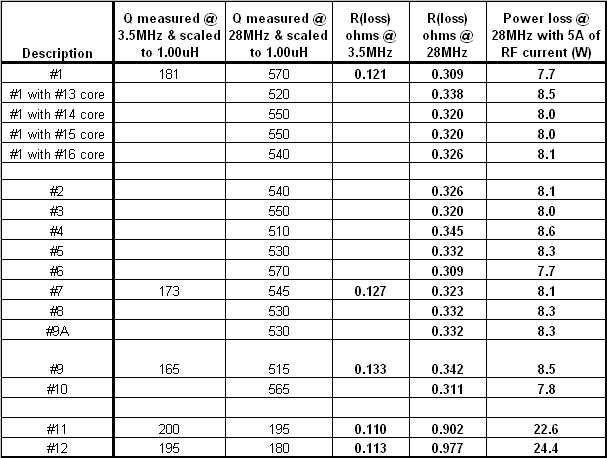
The measurements were made on an HP4342A Q meter that measures Q up to 70 Mhz. Attempts were made to have all the inductors be 1.00 uH but it was difficult to get them much closer than a couple percent. Fortunately slight variations in inductance cause predictable changes in Q since the coil format changed very minimally and the amount of wire in the coil did not change at all. Therefore all the measured Q's were normalized for 1.00 uH. Also the 2 inductors on the powdered iron coils were scaled to 1.00 uH since they were much harder to adjust. The Q's were measured at 3.5 Mhz for some of the coils and at 28.0 Mhz for all of the coils where 1.00 uH represents 176 ohms of inductive reactance.


Conclusions
The air core inductors were measured well below their self resonant frequency which was about 140-150 Mhz. The expected increase in Q from 3.5 Mhz to 28 Mhz matched the measurements well and is due to the inductive reactance increasing linearly with frequency and the skin depth decreasing inversely to the square root of frequency resulting in an increase in Q of approximately the square root of 8 when the frequency was increased 8 times. The 2 inductors wound on the powdered iron torroids had slightly higher Q's at 3.5 Mhz than the air core inductors due to the shorter lengths of wire needed to achieve 1.0 uH but the losses in these cores showed up at 28 Mhz.
However the expected reductions in Q for inductors #2 thru #5 which used weathered wire did not happen. Additionally wire insulation, shrink tubing, paint, and inside support cores (#13 thru #16) all had amazingly little effect on the Q. The column on the right in the above table shows less than a 1 watt difference in the expected power dissipation in the air core inductors with 5A of RF current flowing at 28 Mhz. These results are quite different from what I would have expected based on material I have read over the years. I tried to include all the usual types of corrosion that happens to copper over time. Inductors #3 and #5 were artificially corroded but the corrosion was heavy and severe. If anyone sees any flaws in these tests I would very much appreciate hearing about them. I did not include any data but large reductions in Q were noticed when metal was brought into proximity of the inductor stressing the importance of giving the inductor space to "breathe" if maximum Q is important. However the covering and/or corrosion on the wire itself had amazingly little effect on the inductor Q. From this data it would appear to be more beneficial to increase the wire size by one wire gauge rather than silver plating. I ended up using bare copper wire for my project.
However the expected reductions in Q for inductors #2 thru #5 which used weathered wire did not happen. Additionally wire insulation, shrink tubing, paint, and inside support cores (#13 thru #16) all had amazingly little effect on the Q. The column on the right in the above table shows less than a 1 watt difference in the expected power dissipation in the air core inductors with 5A of RF current flowing at 28 Mhz. These results are quite different from what I would have expected based on material I have read over the years. I tried to include all the usual types of corrosion that happens to copper over time. Inductors #3 and #5 were artificially corroded but the corrosion was heavy and severe. If anyone sees any flaws in these tests I would very much appreciate hearing about them. I did not include any data but large reductions in Q were noticed when metal was brought into proximity of the inductor stressing the importance of giving the inductor space to "breathe" if maximum Q is important. However the covering and/or corrosion on the wire itself had amazingly little effect on the inductor Q. From this data it would appear to be more beneficial to increase the wire size by one wire gauge rather than silver plating. I ended up using bare copper wire for my project.
Problem
Inductor Q Tests
Update Sep. 7, 2011
I did one final test with a piece of bare #10 copper wire that had been buried in a flower bed for about 5 years and had layed on the ground for another 5 years in Colorado. During this time the wire was watered from the lawn sprinkler system, subjected to fertilizer periodically, and to the environment. The surface of the wire, as seen in the picture to the right, had a browish-green hue and was no longer smooth. The wire was wound into the same size coil as was done for the original experiment and measured on the same HP4342A Q meter at 28MHz. The Q was 550 which was virtually the same as the original coil with shiny new copper wire.

Click on picture for larger image
Click on picture for larger image