Page content last updated Jul. 20, 2012
Copyright © 2012 Larry Benko, W0QE
Relay Operate and Release Tester
Relays in radio equipment
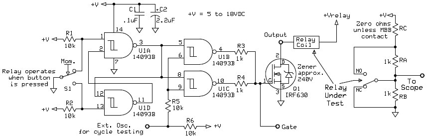
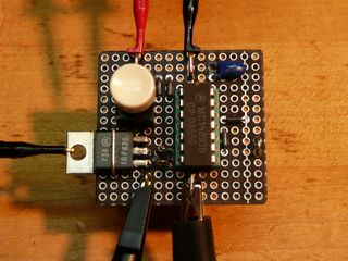
Mechanical relays have not been replaced by solid state switches in many communication designs. Relays are much better than solid state switches in signal paths where intermodulation distortion is important, are less susceptable to ESD and electrical surges, and handle temporary over-current conditions much better but have significant operate and release times and the contacts bounce when switching. The designer of a circuit that includes relays needs to be aware of the operate, release, and bounce times and accomodate for them in the design. Attempts to speed up operate times need to be measured since temporarily increasing the coil current or voltage will reduce the travel time of the transfer contact but may increase the bounce time unacceptably. Release times are always quoted without protection diodes across the relay coil but are seldom used without any protection for the driving device. I built a simple circuit recently to easily make measurements on several relays. The circuit is shown below and in the picture. Resistors RA and RB are external and clipped onto the relay contacts.
U1A and U1D form a flip-flop which removes any bounce in the momentary push button switch S1. U1B and U1C in parallel drive the IRF630 MOSFET which has a built in zener diode which is guaranteed to be greater than 200V. This zener protects the IRF630 while allowing relay release times within a few tens of microseconds compared to releasing the relay with a bare switch. The effects of a conventional diode across the relay coil, a low voltage zener to ground, a series resistor/capacitor across the relay coil, etc. on the relay release time can be easily measured. Resistors RA and RB across the relay contacts allow the scope to "see" the movement of the contacts. See the waveform drawing below. In the unlikely event that a make before break (MBB) relay contact is being measured, resistor RC is needed to keep from shorting +V to ground. There are very few MBB relays available that are common so it is unlikely that one will be used. Since MBB relays briefly short all the contacts their use is quite limited. One example of a MBB relay is the OMRON G2A-4L32A. For long term testing, a pulse generator can be connected to the Ext. Osc. input.
Waveforms
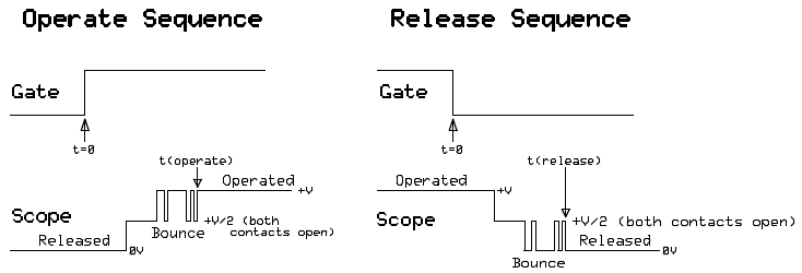
The drawing below shows typical waveforms of a relay being tested. The times t(operate) and t(release) are defined as the minimum time where all contact bouncing has ceased. The relay is cycled 20 to 50 times to get this time as there is some variability. Adding some additional time and/or measuring several relay samples will produce an even better and more conservative value. If you want to be extremely thorough a 10 Hz square wave can be applied to the Ext. Osc. input and the relay can be toggled for a few days. Testing for 24 hours at 10 Hz equates to 864,000 operations of the relay. Some cheap relays may show operate and release time differences after some moderate number of cycles but most of the relays I have tested show very little differences after 5 to 10 million cycles. This of course is a test of the basic relay mechanics and NOT a test of the contacts under the voltage and current conditions in the actual circuit.
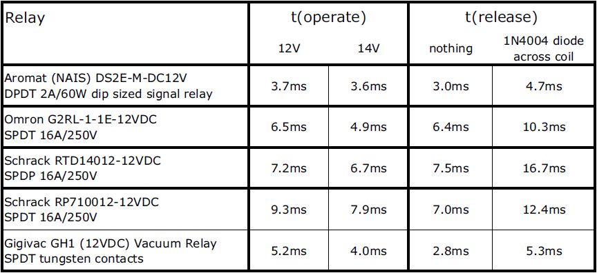
Some measured times