Page content last updated Jul. 16, 2012 (orig. content 2008, 2010)
Copyright © 2008-2012 Larry Benko, W0QE
The following measurements were made on some Icom radios and an Elecraft K2/100 but all radios have the same issues. Since almost everyone uses the same antenna for both transmitting and receiving, an external amplifier must be switched in and out of the circuit when going from transmit to receive. The timing of this switching is important if we expect relays to not be damaged and if we want our transmitted signals to be spectrally clean. The amplifier (or any other devices that may be switched in or out) must be in the circuit BEFORE any RF begins and must not be switched out of the circuit until the RF has totally ceased and then need to be switched out quickly.
The drawing below shows the basic timing external to the radio. The HSEND line is both an input and output but when it is low the radio is in transmit mode and when it is high the radio is in receive mode. The CW key line is shown but is not important to understand the timing as it follows the HSEND line very closely and obviously has is not applicable to any mode other than CW.
Amplifiers are generally controlled via the Send Control jack which is a bare relay contact but may also be controlled via the HSEND output driving an external buffer device. As the following drawing shows the amplifier is given time T3 (or T3-T2) warning to get in the circuit on transmit and the radio goes back to receive T7 after the RF stops. If the amplifier is not ready when the RF begins relays may be damaged and the transmitted signal will have an extremely fast rise time producing spurious signals (splatter or key clicks) and if the amplifier is too slow when switching out of the circuit the radio will be sluggish on having the antenna connected for receive and you will miss the first syllable of speech or the first character on CW.
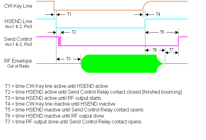
Since the radios are controlled by microprocessors the timing has some small variability as is shown in the following table. Please note that T7 is negative for the IC706mkIIg and the IC7000 in full QSK mode. See the section for the IC7000 below.
Radio T1 T2 T3 T4 T5 T6 T7
Icom 746Pro .1-.4mS .25-.3mS 10-11mS .2-.4mS 14-16mS 8-9mS 6-7mS
Icom 756Pro .1-.3mS .2-.25mS 10-11mS .1-.2mS 11-12mS 5-5.5mS 6-7mS
Icom 706mkIIg 2.8-3.8mS N/A 12-13mS 1.6-3.0mS N/A N/A -4.5mS
Icom 7000 .15-.35mS N/A 7.5-9mS 5mS** N/A N/A -5.5mS
Elecraft K2/100 0mS* 2.2-3.8mS 11-19mS 0mS* 25-29mS ~T5-5mS 4-5mS
* Note: Since the K2 has no equivalent signal to the HSEND line, the CW key line is equated to the HSEND line for the timing measurements.
** Time was hard to measure since CW key line had slow rise time due to capacitance on line inside IC7000.
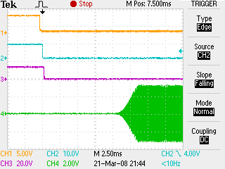
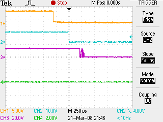
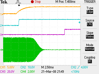
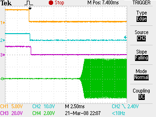
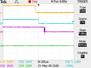
Waveforms for Icom 746Pro being operated at 14.1MHz, 100W into dummy load, full QSK, 4mS CW rise time.
For these 3 waveforms, the orange trace is the CW key line, the cyan trace is the HSEND line, the purple trace is the Send Control relay output connected to a 4.7k ohm resistor to 13.8VDC, and the green trace is the RF envelope. The waveform at the right shows the transmit delay at 2.5mS per scope division. The waveform directly below shows the same event but at 250uS per division to show the relay bounce and the small delays between the CW key line, HSEND, and the Send Control relay. The waveform below right shows the transition back to receive at 2.5mS per division.
For these 3 waveforms, the orange trace is the CW key line, the cyan trace is the HSEND line, the purple trace is the Send Control relay output connected to a 4.7k ohm resistor to 13.8VDC, and the green trace is the RF envelope. The waveform at the right shows the transmit delay at 2.5mS per scope division. The waveform directly below shows the same event but at 250uS per division to show the relay bounce and the small delays between the CW key line, HSEND, and the Send Control relay. The waveform below right shows the transition back to receive at 2.5mS per division.
Icom 746Pro Timing
Icom 756Pro Timing
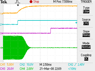
Waveforms for Icom 756Pro being operated at 14.1MHz, 100W into dummy load, full QSK, 4mS CW risetime. Note that the 756 Pro has a faster RF rise time even though both radios were set the same. Also note that the 756Pro shuts off the RF slightly quicker than the 746Pro.
For these 3 waveforms, the orange trace is the CW key line, the cyan trace is the HSEND line, the purple trace is the Send Control relay output connected to a 4.7k ohm resistor to 13.8VDC, and the green trace is the RF envelope. The waveform at the right shows the transmit delay at 2.5mS per scope division. The waveform directly below shows the same event but at 250uS per division to show the relay bounce and the small delays between the CW key line, HSEND, and the Send Control relay. The waveform below right shows the transition back to receive at 2.5mS per division.
For these 3 waveforms, the orange trace is the CW key line, the cyan trace is the HSEND line, the purple trace is the Send Control relay output connected to a 4.7k ohm resistor to 13.8VDC, and the green trace is the RF envelope. The waveform at the right shows the transmit delay at 2.5mS per scope division. The waveform directly below shows the same event but at 250uS per division to show the relay bounce and the small delays between the CW key line, HSEND, and the Send Control relay. The waveform below right shows the transition back to receive at 2.5mS per division.
Icom 706mkIIG Timing
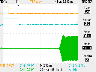
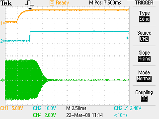
Waveforms for Icom 706mkIIG being operated at 14.1MHz, 100W into dummy load, full QSK, no CW risetime option. Note that the 706 has no Send Control relay output and an interface must be used to connect from the HSEND line to the amplifier if not using an Icom amplifier.
For these 2 waveforms, the orange trace is the CW key line, the cyan trace is the HSEND line, and the green trace is the RF envelope. The waveform below left shows the transmit delay at 2.5mS per scope division. The waveform below right shows the transition back to receive at 2.5mS per division. Notice that the HSEND line goes inactive 4.5mS before the RF stops which possibly could be a big problem. Operating in standard break-in mode ALWAYS has the HSEND line active after the RF stops similar to the IC7000.
For these 2 waveforms, the orange trace is the CW key line, the cyan trace is the HSEND line, and the green trace is the RF envelope. The waveform below left shows the transmit delay at 2.5mS per scope division. The waveform below right shows the transition back to receive at 2.5mS per division. Notice that the HSEND line goes inactive 4.5mS before the RF stops which possibly could be a big problem. Operating in standard break-in mode ALWAYS has the HSEND line active after the RF stops similar to the IC7000.
Elecraft K2/100 Timing
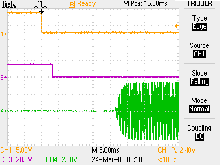
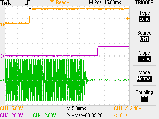
Waveforms for Elecraft K2/100 at 14.1MHz, 100W into dummy load, full QSK, no CW risetime option.
For these 2 waveforms, the orange trace is the CW key line, the purple trace is the AMP key line with a 4.7k ohm resistor connected to 13.8VDC, and the green trace is the RF envelope. The waveform below left shows the transmit delay at 5.0mS per scope division. The waveform below right shows the transition back to receive at 5.0mS per division.
For these 2 waveforms, the orange trace is the CW key line, the purple trace is the AMP key line with a 4.7k ohm resistor connected to 13.8VDC, and the green trace is the RF envelope. The waveform below left shows the transmit delay at 5.0mS per scope division. The waveform below right shows the transition back to receive at 5.0mS per division.
Icom 7000 Timing
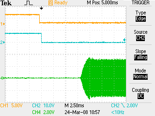
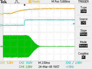
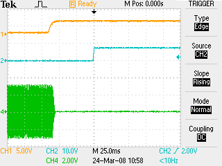
Waveforms for Icom 7000 being operated at 14.1MHz, 100W into dummy load, 4mS CW risetime. The top 2 waveforms are for the full QSK mode and the bottom one is for standard break-in mode at 60 WPM and delay time set to 2.0 dot times which is the minimum setting. Note that the 7000 has no Send Control relay output and an interface must be used to connect from the HSEND line to the amplifier if not using an Icom amplifier.
For these waveforms, the orange trace is the CW key line, the cyan trace is the HSEND line, and the green trace is the RF envelope. The waveform below left shows the transmit delay at 2.5mS per scope division. The waveform below right shows the transition back to receive at 2.5mS per division. Notice that if operating in full QSK mode the HSEND line goes inactive 5mS before the RF stops which possibly could be a big problem. Operating in standard break-in mode, for all delay times, has no such issues and note that the bottom waveform is shown at 25mS per division.
For these waveforms, the orange trace is the CW key line, the cyan trace is the HSEND line, and the green trace is the RF envelope. The waveform below left shows the transmit delay at 2.5mS per scope division. The waveform below right shows the transition back to receive at 2.5mS per division. Notice that if operating in full QSK mode the HSEND line goes inactive 5mS before the RF stops which possibly could be a big problem. Operating in standard break-in mode, for all delay times, has no such issues and note that the bottom waveform is shown at 25mS per division.
Amplifier Timing
Icom 7200 Timing
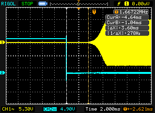
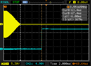
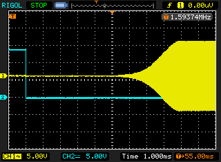
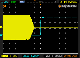
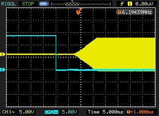
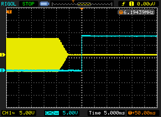
The time from relay active to the start of RF is a very quick 3.6ms. which might cause some problems with hot switching some amplifiers. Using the solid state buffer on the HSEND line in the ACC connector increases this time to a more reasonable but still fairly quick 5.5ms. The hold times after the end of the RF are fine since any time greater than 0ms. is acceptable.
Thanks to Jim, W7RY for providing the scope data for the IC-7200 transceiver.
Thanks to Jim, W7RY for providing the scope data for the IC-7200 transceiver.
IC-7200 3.6ms send relay close to RF start
IC-7200 6.0ms. RF stop to send relay open
IC-7200 5.5ms. transistor active to RF start
IC-7200 5.0ms. RF stop to transistor inactive
Icom 7600 Timing
The IC-7600 scope outputs are shown for the 4ms. CW rise and fall time setting. The lead time before the start of the RF output is a very typical 8ms. and the hold time after the RF is fine at 5ms.
I have received 2 reports that the IC-7600 has a negative hold time for the RF stop time similar to the IC-706mkIIG and the IC-7000 but these scope plots do not show such behavour. Perhaps this problem existed in an early version of the firmware or that the reports were incorrect. The serial number of the tested transceiver was 0201871 and the firmware version was 1.11.
Thanks again to Jim, W7RY for providing the scope data for the IC-7600 transceiver.
IC-7600 8ms send relay close to RF start
IC-7600 5ms RF stop to send relay open
