What is Being Tested?
Mobile Shootout 2011
Page content last updated Oct. 16, 2011
Copyright © 2011 Larry Benko, W0QE
Comparison tests of signal strengths from mobile setups are generally called "shootouts" and often "antenna shootouts". However in a mobile setup the antenna can not be separated from the vehicle and as such the test is more correctly a measure of the antenna, antenna placement on the vehicle, and vehicle size/shape. Additionally issues such as transmitter power output, matching the transmitter to the antenna, loss in the coax. loss in a tuner if used are all included in the comparison since the recieving station only hears what power was radiated. I made power output measurements of an Icom 706mkII-g and Icom IC-7000 for various DC input voltages and various SWRs which can be viewed by clicking here.
Why Do Anything Differently?
Generally shootouts have the mobiles locate their vehicle or antenna at a fixed point and then transmit to a measuring station that is located a few hundred feet away. The mobiles often will operate on more than 1 band and rotate the vehicles to see the directionality of the setup. The receiving station uses a small vertical or loop antenna connected to a field strength meter or spectrum analyzer and measures the mobile signal. Sometimes effort is made to ensure that everyone uses the same power level as all 100W radios do vary slightly in power due to the radio itself, the delivered DC powering voltage and RF impedance presented to the radio.
There are two weaknesses with tests done in this manner:
1.) Taking a field strength measurement at a takeoff angle of close to 0 degrees and extrapolating that to be directly proportional to the field strength at a takeoff angle that is used for normal communication.
2.) Capturing the signal strength with a single antenna of any polarization may not measure the total signal field strength. Two antennas capturing orthogonal polarizations, with the outputs summed, captures the total field strength. This is important as most mobile setups contain both vertical and a significant amount of horizontal polarization.
These two concerns were addressed in a previous mobile test I did and the results in a pdf file can be viewed by clicking here.
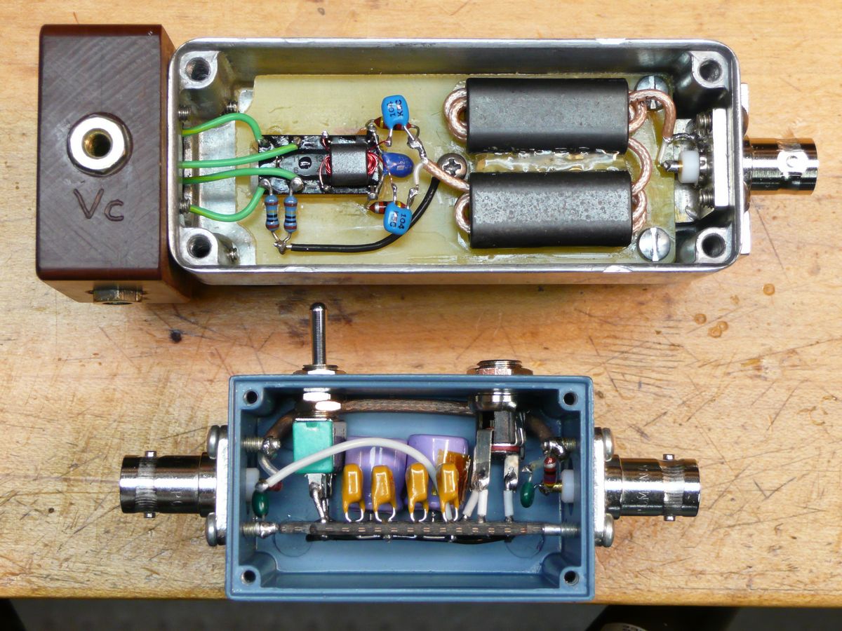
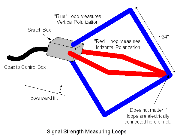
Click here for a pdf schematic of the circuitry or click on any picture for a higher resolution image.
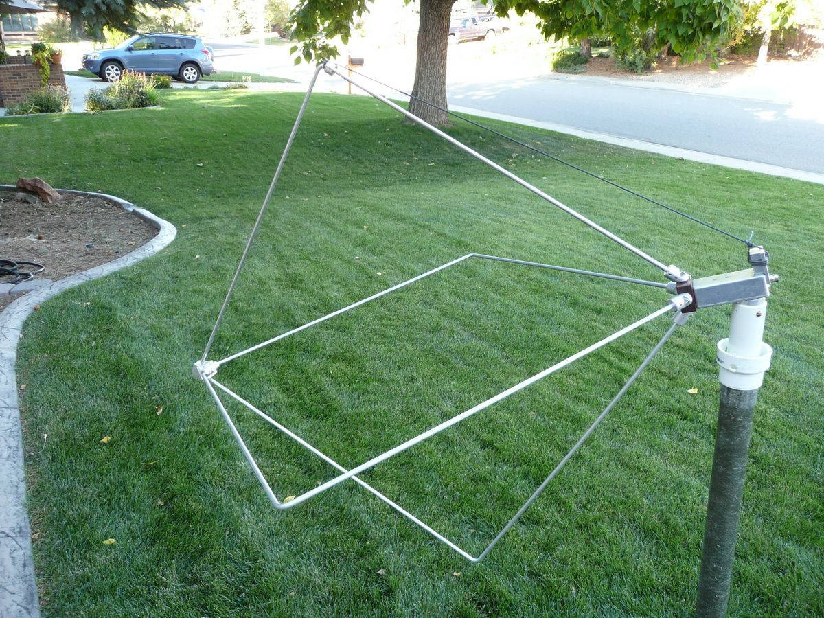
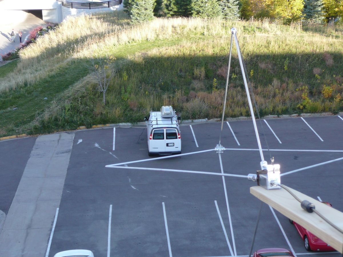
The picture above shows the switch box (top) without the rectangular loop antennas connected and the control box (bottom). The control box sits near the spectrum analyzer or calibrated receiver, is powered by 12VDC, and remotely powers a relay in the switch box. This relay switches between the two loops to select either the vertically or horizontally polarized loop. The upper right picture shows the switch box and the 2 loops assembled while the picture on the lower right shows the assembly looking downward at a 20 degree angle to the mobile vehicle under test.
Test Setup
The antenna used to capture the mobile signal is shown below. When tilted downward it not longer captures exactly vertical and horizontal polarizations but it does still capture 2 orthogonal polarizations which is what is required. This antenna produces maximum output powers of approximately -13dBm for 100W mobiles at a distance of 150 ft. over all frequencies from 80m thru 10m. If mobiles are allowed to transmit on any frequency within a band, and comparisons are wanted, an antenna correction of 0.35dB/100KHz (80m), 0.20dB/100kHz (40m), and 0.10dB/100kHz on 20m needs to be applied since the loop becomes more sensitive as the frequency is increased. Signals from the two loops are measured in dBm, converted to watts, added, and then converted back to dBm. For these tests a 20dB attenuator was inserted before the receiver. Then if necessary a small band correction is applied so participants do not need to retune their mobile antennas prior to being measured. All transmitters were set at 100W but were not verified for low DC input voltage or SWR foldback.
Results
Thanks to N0QO for collecting the data.
No Picture!
(Please note that -30dBm is 1dB stronger signal than -31dBm)